Tune Control Design for VTOL UAV in Hover Configuration
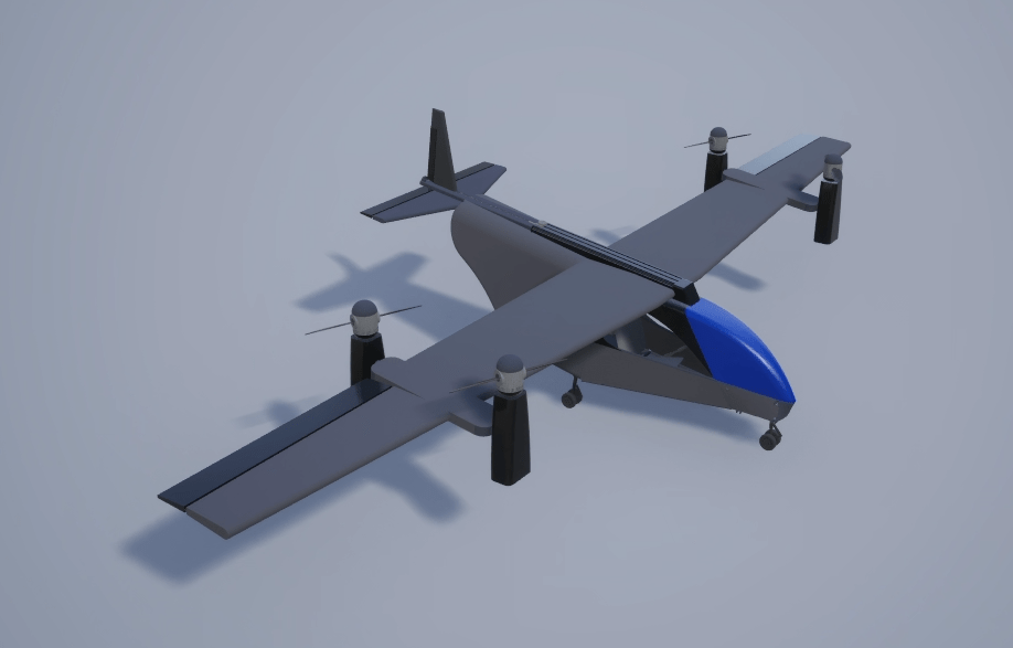
This example shows how to tune the hover controller of a tilt-rotor VTOL UAV. In the hover configuration, the pitch of the VTOL UAV is stabilized to 0 degrees to minimize interference from wing aerodynamic effects. To move forward and backward in hover mode, the VTOL UAV tilts the front two rotors in unison. To move laterally, the VTOL UAV rolls by increasing the RPM of the rotors on one side of the VTOL UAV, similar to a quadcopter. To control yaw, the VTOL UAV differentially tilts the front two rotors.
Getting Started
To access the Simulink model, supporting files, and project shortcuts that this example uses, open the VTOLRefApp.prj project file.
% Open the Simulink project
prj = openProject("VTOLApp/VTOLRefApp.prj");
To set up the VTOL UAV plant and enable the hover configuration, on the Project tab of the MATLAB Toolstrip, in the Shortcuts section, click the Set up Plant button. Alternatively, use the setupPlant helper function. Setting up the plant loads the baseline hover controller gains stored in utilities/Setup/exampleHelperInitializeVTOLGains.m.
setupPlant
Initialized VTOL model.
Enabled hover configuration.
Enabled hover guidance mission.
Verify Baseline Hover Controller Gains with Manual Control
To enable manual control, in the Hover section of the project Shortcuts, select Manual Mode. Alternatively, use the setupHoverManual helper function.
setupHoverManual
Enabled hover manual testbench mode.
Open the VTOLTiltrotor.slx model.
open_system("VTOLTiltrotor")Run the model, and open the Manual Control Dashboard subsystem.
 .
.
Adjust the Hover Commands sliders to manually select the setpoints for the X, Y, and altitude values. Observe that the VTOL UAV follows the setpoints that you select.
Verify Baseline Hover Controller Gains with Guidance Mission
The VTOL UAV reference application enables you to use a hover guidance mission to verify the hover controller gains, which ensures that the VTOL UAV is able to follow more aggressive setpoints during operation in an urban environment. During the guidance mission, the Guidance Test Bench subsystem calculates the hover controller setpoints based on the mission and the current state of the UAV.
To set up a hover guidance mission that consists of takeoff, waypoint navigation, and landing, in the Hover section of the project Shortcuts, select Guidance Mode. Alternatively, use the setupHoverGuidanceMission helper function.
setupHoverGuidanceMission
Enabled hover guidance mission.
Disable the visualization subsystem to speed up the simulation.
Visualization = 0;
Run the VTOLTiltrotor model and store the output in outBaseline.
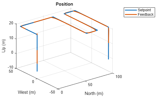
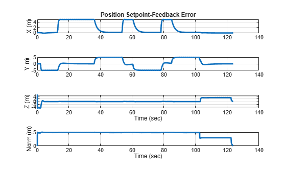
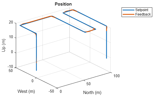
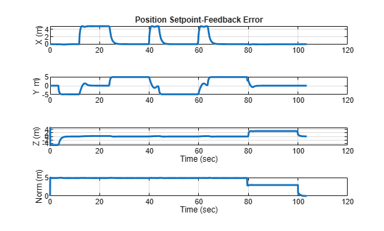
outBaseline = sim("VTOLTiltrotor");Use the exampleHelperPlotHoverControlTrackingResults helper function to create 2D and 3D plots of the position setpoint and feedback, as well as the position setpoint-feedback error. The plots indicate that by using the baseline gains, the hover controller is able to track the position setpoints during the mission, and that the VTOL UAV completes the mission in approximately 125 seconds.
exampleHelperPlotHoverControlTrackingResults(outBaseline)

Selecting a more aggressive controller gains allows the VTOL UAV to take more aggressive maneuver, which enables it to complete the mission faster. However, controller gains that are too aggressive can make the VTOL UAV unstable.
Automatic Tuning of Hover Controller Gains
The VTOL UAV hover controller consists of these cascading controller loops:
Attitude rate controller — Innermost loop, consisting of the pitch rate, roll rate, and yaw rate PID controllers.
Attitude controller — Pitch, roll, and yaw PID controllers.
Velocity controller — X-, Y-, and Z- velocity PID controllers.
Position controller — Outermost loop, consisting of the X-, Y-, and Z- position PID controllers.
To improve the hover controller performance, you must adjust the proportional, integral, and derivative gains, along with a filter coefficient, for each controller in the loop. This requires you to tune 48 parameters in total.
The automatic tuning process enables you to obtain the controller gains without having to perform multiple simulations to iterate each of the 48 parameters, which saves you time during the hover controller design process. In this example, the target phase margin for all controllers in the automatic tuning process is 60 degrees, to balance between stability and response time.
Before starting the automatic tuning process, you must enable manual control by selecting Manual Mode from the Hover section of the project shortcuts, or by using the setupHoverManual helper function.
setupHoverManual
Enabled hover manual testbench mode.
The automatic tuning process linearizes the VTOL UAV system around the hover condition. Reset the hover commands to enable linearization of the system in the hover condition.
set_param("VTOLTiltrotor/Manual Control Dashboard/Slider1","Value","10")
set_param("VTOLTiltrotor/Manual Control Dashboard/Slider2","Value","0")
set_param("VTOLTiltrotor/Manual Control Dashboard/Slider3","Value","0")
Run the exampleHelperAutomatedHoverControlTuning script to start the automatic tuning process by running this command in the Command Window.
exampleHelperAutomatedHoverControlTuning
During the automatic tuning process, the exampleHelperAutomatedHoverControlTuning script performs these operations in each loop, starting from the innermost loop and moving to the outermost loop:
Obtain the linearization input and output points.
Linearize the system using
linearize.Obtain PID controller gains using
pidtune.Write the tuned gains to the workspace.
The automatic tuning process can take some time. To load a pregenerated tuning result, load the tunedHoverGains_BW50 MAT file.
load tunedHoverGains_BW50Verify Tuned Hover Controller Gains with Guidance Mission
Verify the hover controller gains that you obtained from the automatic tuning process by using the hover guidance mission.
Set up a hover guidance mission that consists of takeoff, waypoint navigation, and landing by clicking Guidance Mode shortcut, or by using the setupHoverGuidanceMission helper function.
setupHoverGuidanceMission
Enabled hover guidance mission.
Disable the visualization subsystem to speed up the simulation.
Visualization = 0;
Run the VTOLTiltrotor model and store the output in outTuned.
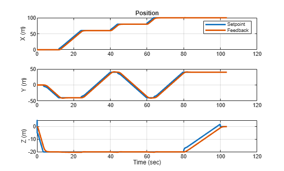
outTuned = sim("VTOLTiltrotor");Use the exampleHelperPlotHoverControlTrackingResults helper function to create 2D and 3D plots of the position setpoint and feedback, as well as the position setpoint-feedback error. The plots indicate that by using the updated gains, the hover controller is also able to track the position setpoints during the mission, and that the VTOL UAV completes the mission in approximately 100 seconds.
exampleHelperPlotHoverControlTrackingResults(outTuned)
Comparison of Mission Time
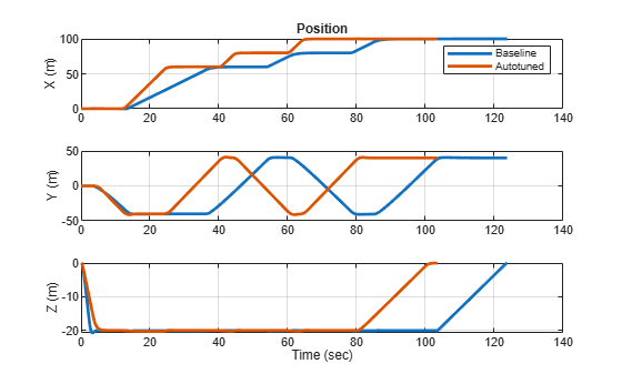
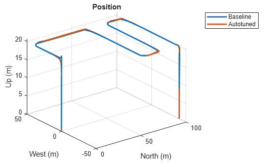
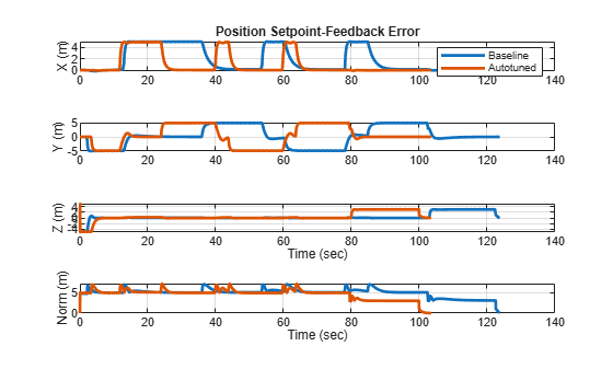
Use the exampleHelperPlotHoverControlTrackingComparison helper function to compare position and position-feedback error between the baseline and automatically tuned gains. The plots indicate that by using the automatically tuned gains, the VTOL UAV completes the mission approximately 25 seconds faster compared to using the baseline gains.
exampleHelperPlotHoverControlTrackingComparison(outBaseline,outTuned)
Before resuming to other examples in this example series, you must close the VTOLRefApp.prj Simulink project by running this command in the Command Window:
close(prj)