Detect CAN Frame Corruption with Cyclic Redundancy Check
This example shows how to use Cyclic Redundancy Check (CRC) to detect corrupted values in the payload of a CAN frame.
Data Integrity and Standardized CRC Algorithms
CRC is used to ensure data integrity across various communication and memory operations. The check is based on polynomial division; specifically, the check value for a payload is obtained as the remainder of the polynomial division of the payload bits with a generator polynomial. The check value is then appended to the payload and transmitted. Upon reception, the receiver computes the check value from the received payload and compares it to the value appended in the message; equal values indicate, with some degree of confidence, that the transmission did not impact the integrity of the data.
In automotive applications, the check is implemented in standardized ways to ensure consistency across ECUs (Electronic Control Units). For example, the SAE J1850 CRC8 algorithm is based on a check value of 8 bits, and a generator polynomial of the form .
CRC Values in CAN Frames Defined in DBC Files
This example deals only with the so-called application-level CRC, which is handled by the application layer; this CRC is unrelated to protocol-level CRC, which is typically managed by hardware or low-level drivers. DBC files do not provide any special handling for application-level CRC. If you need to include a CRC check value in a CAN message, you must reserve specific bits within the message and define the CRC as a regular signal in the DBC file.
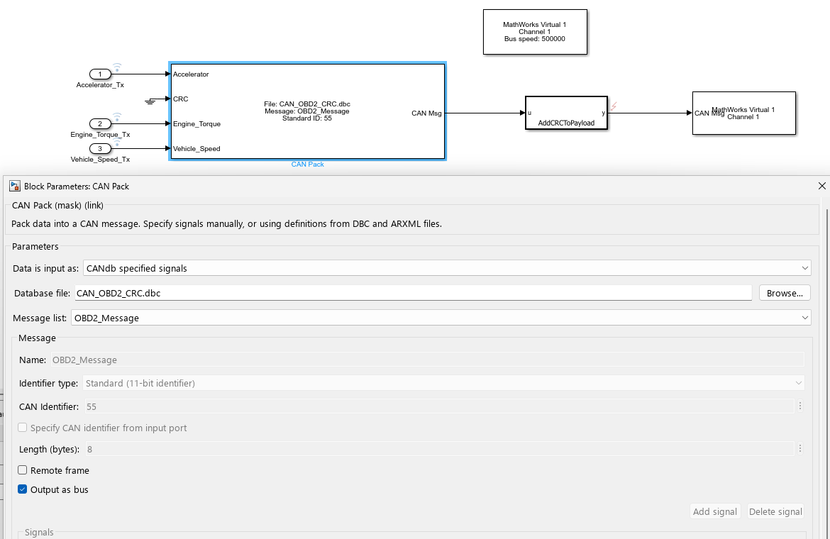
The example provides the file CAN_OBD2_CRC.dbc, that defines one message with length 8 bytes, carrying three OBD signals in the first 3 bytes, and a CRC signal in the eighth byte.
db = canDatabase("CAN_OBD2_CRC.dbc");
struct2table(db.MessageInfo.SignalInfo)ans=4×20 table
Name Comment StartBit SignalSize ByteOrder Signed ValueType Class Factor Offset Minimum Maximum Units ValueTable Multiplexor Multiplexed MultiplexMode RxNodes Attributes AttributeInfo
_________________ __________ ________ __________ ________________ ______ ___________ _________ ______ ______ _______ _______ __________ ____________ ___________ ___________ _____________ __________ __________ _____________
{'Accelerator' } {0×0 char} 8 8 {'LittleEndian'} true {'Integer'} {'int8' } 1 0 -100 100 {0×0 char} {0×1 struct} false false 0 {0×1 cell} {0×0 cell} {0×0 struct}
{'CRC' } {0×0 char} 56 8 {'LittleEndian'} false {'Integer'} {'uint8'} 1 0 0 0 {0×0 char} {0×1 struct} false false 0 {0×1 cell} {0×0 cell} {0×0 struct}
{'Engine_Torque'} {0×0 char} 0 8 {'LittleEndian'} false {'Integer'} {'uint8'} 1 0 0 100 {'rpm' } {0×1 struct} false false 0 {0×1 cell} {0×0 cell} {0×0 struct}
{'Vehicle_Speed'} {0×0 char} 16 8 {'LittleEndian'} false {'Integer'} {'uint8'} 1 0 0 100 {'km/h' } {0×1 struct} false false 0 {0×1 cell} {0×0 cell} {0×0 struct}
Computation of the CRC Value and Update of the Message Before Transmission
The CRC value is computed based on the payload which, in turn, depends on the signal values. One way to proceed in Simulink® is to apply the regular encoding of the message while keeping the input value of the CRC as zero, then adding the CRC value to the message after packing, as shown in the following diagram.
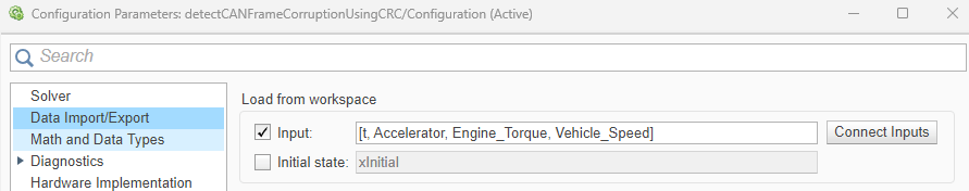
This diagram is part of the model detectCANFrameCorruptionUsingCRC, which is parameterized with sample time, stop time and input data as shown in the code below.
open_system("detectCANFrameCorruptionUsingCRC.slx");
Ts = 0.1;
StopTime = 10;
load("input_data.mat");
The input data is defined through Inport blocks, therefore the input signals are specified in the Configuration Parameters as follows:
The CAN Pack block is configured to output a bus of type CAN_MESSAGE_BUS. The MATLAB® function AddCRCToPayload expects a corresponding bus type, and modifies the Data field in the bus by computing the CRC value from the first 7 bytes, and adding the value to the 8th byte. The bus object can be created in the MATLAB workspace with the following call:
canMessageBusType;
The computation of the check value in the MATLAB function AddCRCToPayload follows a standard methodology; see, for instance, Perform Cyclic Redundancy Check.
The architecture proposed here is for illustrative purposes only. In particular, in a more realistic setting the coupling between the AddCRCToPayload MATLAB Function block and the DBC file can be managed by having the two blocks within a masked subsystem, and having them parameterized based on the DBC file's contents from the subsystem's mask callback.
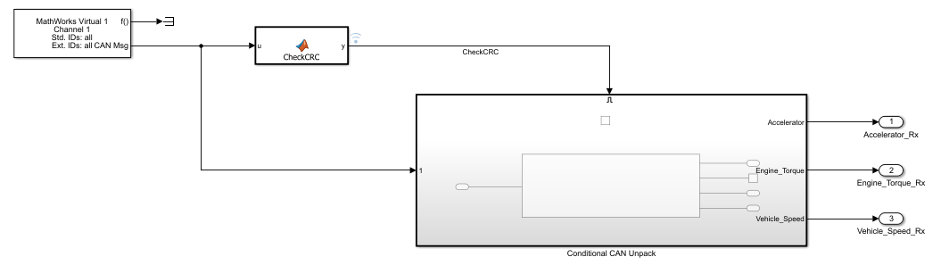
Integrity Check of the Message
Upon reception, the MATLAB function CheckCRC computes the check value based on the payload, and returns true if the value is equal to the value received in the message. This boolean output is, in turn, used to conditionally control the CAN Unpack block, so that processing of incoming messages is interrupted if an invalid CRC value is detected.
Simulation of Transmission Faults
The CAN Transmit and CAN Receive blocks, when configured to use a virtual channel, simulate the transmission using a software buffer, which does not corrupt the data. It is possible to simulate the data corruption process by introducing a custom fault in the transmitted signal message.
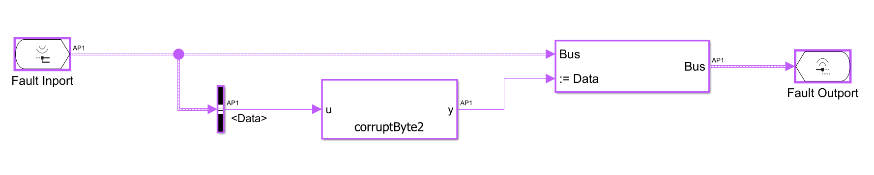
In this example, the fault acts on the output of the MATLAB function AddCRCToPayload, and it is activated at simulation time t = 5 sec.
The fault model diagram, stored in the model detectCANFrameCorruptionUsingCRC_FaultModel and accessible from the Simulink Fault Analyzer™ interface, is shown in the following figure. The payload corruption is implemented using a MATLAB function corruptByte2, which flips a random bit in byte 2 of the payload.
An additional XML file detectCANFrameCorruptionUsingCRC_faulInfo.xml is used by Simulink Fault Analyzer to store the fault metadata.
After simulation of the model, inspection of the signals shows that the output of the Conditional CAN Unpack subsystem matches the (quantized) input up to 5 sec, then drops to zero (the default value) due to the CRC being invalid. The output of the CAN Unpack block is quantized because the DBC file specifies 8-bit integers for the representation of the signals.
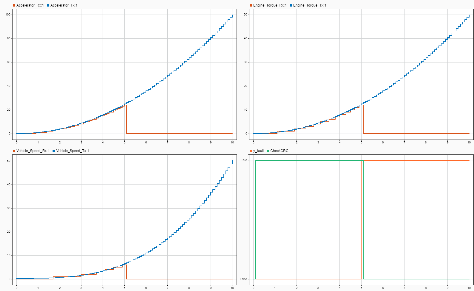
In the figure above, the CheckCRC signal shows a delay of one timestep compared to the fault trigger. This is due the execution order of the blocks in the model: at a given time, the CAN Receive block is executed before the CAN Transmit block. In particular, at t = 0 sec, the CheckCRC signal is false because the CAN Transmit block has not transmitted anything, while the CAN Receive block has received an empty frame, for which the CRC is not matching; the correct frame is received in the next time step. Similarly, when the fault is triggered at t = 5 sec, the CheckCRC signal is updated at t = 5.1 sec, that is, one timestep later than the fault trigger time.