Results for
I am using Mathlab/simulink R2023b and PSIM2022.1.
I am trying to do co-simulación betwen simulink and PSIM of multiport controlled inverters. In Simulink, when I add the simcoupler block and double clik in it to set the path, that windows is opened, but when browse the path of PSIM schematic file and then clik APPLY, suddenly Simulink closes. Could somebody give some clue How to solve this issue.
NOTE: I tried as well the example of the tutorial of simcoupler module but the problem is the same.
How can I mechanically couple synchronous reluctance motor from simscape electrical electromechanical library and dc generator from specialized power system library
I was given a homework to make a Simscape IGBT rectifier, in which changing the delay angle leads to the conventional output. The input is 220 V 50 Hz supply, there are 2 gate pulses which I am providing using pulse generators (period 1/50 and pulse width 50%). The output, however is not correct. I am attaching the circuit diagram
and the incorrect output for a delay angle (α) 60 degrees. Can somebody point out the mistake? Thank you.
Hello everyone,
I have an EV model, and I would like to calculate its efficiency, i.e., inverter efficiency, motor efficiency and motor efficiency, and I would also like to draw its efficiency map. What approaches can I use to achieve the said objectives.
For now,
- I have connected a power sensor at the battery side, which provides a average power at 0.001 sec.
- A three-phase power sensor at inverter's output, which apparantly provides higher power than input.
- A rotational power sensor, which also provides averaged mechanical power at 0.001 sec.
Following are the challenges which I am facing.
- Higher inverter power.
- Negative power as well, depending on the drive cycle especially when torque is negative during deceleration.
I am attaching the EV model. Your guidance on this will be highly appreciated.
Hi everyone,
I need deep orientation to make calculation of speed and Angle for the absolute encoder RM22SC with signal (data+, Data-, Clock +, Clock -) using Launchpad F28379D and Simulink.
I did interface the absolute encoder with IC DS26LS32CN and I did get signal Data and Clock. I did use the GPIO20 for Data and GPIO21 for Clock and connect both to the Matlab Function block to get as output the position. See the code on attached. The output of the Matlab function times 2*pi/8192 to get the angle. However, I don't get anything as value.
Matlab Fuction Block code
function position = decodeSSI(data, clock)
%#codegen
persistent bitCounter shiftRegister prevClock
if isempty(bitCounter)
bitCounter = uint32(0);
shiftRegister = uint32(0);
prevClock = uint32(0);
end
% Parameters
numBits = 13; % Number of bits in the SSI word
% Rising edge detection for clock
clock = uint32(clock); % Ensure clock is of type integer
clockRisingEdge = (clock == 1) && (prevClock == 0);
prevClock = clock;
if clockRisingEdge
bitCounter = bitCounter + 1;
% Shift in the data bit
shiftRegister = bitor(bitshift(shiftRegister, 1), uint32(data));
% Check if we have received the full word
if bitCounter == numBits
position = shiftRegister;
% Reset for the next word
bitCounter = uint32(0);
shiftRegister = uint32(0);
else
position = uint32(0); % or NaN to indicate incomplete data
end
else
position = uint32(0); % or retain the last valid position
end
end
hello i'm working on simulation using simulink which is my title is ENHANCING BATTERYENERGY STORAGE SYSTEMSTHROUGH MODULAR MULTILEVEL CONVERTER WITH STATE-OF-CHARGE BALANCING CONTROL. i already build 9 level mmc. but i dont have any idea for state of charge balancing control.please any suggestion and explain.
Any one have deep learning reinforcement based speed control of induction motor?
错误使用 ipqpdense
The interior convex algorithm requires all objective and constraint values to be finite.
出错 quadprog
ipqpdense(full(H), f, A, B, Aeq, Beq, lb, ub, X0, flags, ...
出错 MPC_maikenamulun
[X, fval,exitflag]=quadprog(H,f,A_cons,B_cons,[],[],lb,ub,[],options);
Cordial saludo , Necesito simular un generador electrico que tiene una entrada mecanica y genera el suficiente voltage y corriente para encender un LED.
how to find out overcoming force in llinear actuator model?
I am using llinear actuator model.Power supply dc is applied to model.i am able to read spring force using force sensor connected with translational spring in series.but I could not find plunger force(Over coming force).So,How to find out plunger force.
Hello Everyone,
I have modelled a FOC using average converter, and the PWM signal is generated using PWM generator (3-phase, 2-level). First, it had error of algebraic loop, but after searching in MATLAB community, I have used unit delay to avoid loop, but still when use local solver option is uncheked in the solver configuration, it still shows algerbaic loop, but when local solver is checked, it works. So, kindly put some light on this issue.
Rught now, the second issue which Im currently facing is " Index expression out of bounds. Attempted to access element 2. The valid range is 1-1." and "Function call failed.
Function 'PWM Generator (Three-phase, Two-level)/Switching Time Calculation' (#59.72.154), line 3, column 1:
"[TgabcON,TgabcOFF,ModWave] = ee.control.pwmSwitchingTimeTwoLevel(Vabc,vdc,fsw,PW"
Launch diagnostic "
I have attached the simulink model hereby. Kindly looking for your expert opinion on how to solve these issues.
Hello everyone.
I have modelled a three phase inverter to run a 5Kw PMSM motor (MATLAB preparametrized). The torque load is applied through ideal torque source and step junction, and the speed of the motor is visualized. When I provide the gate signal only through SPWM generator (No control, only SPWM signal generation through carrier and sine wave comparison),
- The speed stabilizes around 62 rad/sec after some initial oscillations, but when I try to run the same model using PMSM field oriented control block set, the speed is negative (negative rotation) and it keeps on increasing eventhough the speed reference provided is only upto 60. The waveform of both speed and torque has been attached hereby.
- Moreover, is there anyway to tune the PI controllers (inner and outer loops) of PMSM Field oriented blockset automatically.
- It can be seen from the torque waveform, there is soemkind of disturbance around 0.4-0.45 sec, which creates too much noise in current, torque waveforms. What could be the reason behind this.
Your help would be highly appreciated.
Thank you.
Hello everyone,
I am currently working on a project to simulate an autonomous energy production plant integrating renewable sources and a hydroelectric generator using MATLAB.
If anyone has experience in this area or can provide advice I would be extremely grateful. Thank you in advance for your precious help !
Hello everyone,
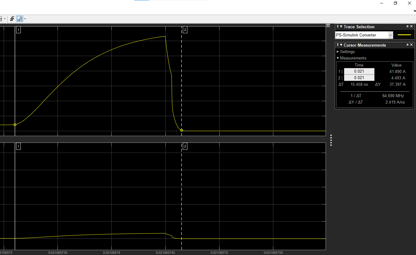
Im trying to simulate an 3-phase inverter, and for analysis of semicondcutor switches cuurent and voltage, I witness some unusal behaviour. I have connected a current sensor to the drain to calculate and visialize drain current, but the waveform is lookibg something like in picture if instaneous overshooting when going form high to low or vice versa, and the magnitude of the overshooting pulse can reach upto 500 Amps.
Kindly, guide me what am i doing here wrong? and one more thing is that I have set the Ids current to be 63Amps for N-channel Mosfet, but the output is 42-44 Amp max, what could be the reason behind it?
Thank you in advance!!
Hello Everyone,
I want to model an electric vehicle in simscape electrical, I have few quiries regarding it.
- I have modelled an 3-Phase inverter, and used ee_getPowerLossSumary to get switching losses, and the results are okay as i was expecting, but now is there any other function to calculate conduction losses?
- I want to connect a BLDC motor, I have few parameters from manufacturers datasheet, but not all the parameters, so what would the best way according to your understanding, to model motor losses (Copper + Core).
I'm trying to calculate major fundamental losses of an EV. Looking for your inputs on this.
Thank you!
I have encountered a problem. I want to study the direction of PHEVP2 configuration energy control strategy, but the whole vehicle model has stumped me. I don't know how to proceed, and every time I run, an error message will be reported. I don't understand where the problem lies?
How to Simulate a Synchronous Compensator in Simulink?
Need help about FPGA Based VSC HVDC Real Time Simulation Model.
I am trying to make a simulink model to use a MPC to reduce power consumption of HVAC system in an electric vehicle during cool down from ambient temperature to a set point temperature. Any help regarding this would be appreciated
Kindly help me correct this code to function properly. I am just learning MATLAB. i cannot get the output in abc frame. This is the code:
%----------- Define input and state parameters-----------------------------
clc
v_dc = 350; % DC input voltage in V
m = 0.841; % modulation index
C = 4000e-6; % DC buss capacitance in uf
L_1 = 2.5e-3; % Inverter side inductance in mH
L_2 = 2.5e-3; % Load side inductance in mH
L = 0; % load inductance
C_f = 10e-6; % filter capacitance in uf
R_f = 0.7; % damping resistance in ohms
R_L = 20; % load resistance in ohms
f_s = 10e3; % switching frequency
f = 60; % System frequency
R_s = 0.01; % Capacitance of the DC circuit
I_d = 8.594; % steady state current
w = 2*pi*f; % System angular Frequency
% Define initial steady state values
v_c = 349.4; i_d = 8.594; i_q = -0.213; v_df = 285; v_qf = -120; i_Ld = 8.594; i_Lq = 0.85;
%------------------S V P W M Generator-------------------------------------
% Define reference vector Uref
U_mag = m*v_dc/2; % Magnitude of Uref
% Define switching vectors
U1 = [v_dc/2;0]; % Vector Q1
U2 = [v_dc/4;sqrt(3)*v_dc/4]; % Vector Q2
U3 = [-v_dc/4;sqrt(3)*v_dc/4]; % Vector Q3
U4 = [-v_dc/2;0]; % Vector Q4
U5 = [-v_dc/4;-sqrt(3)*v_dc/4]; % Vector Q5
U6 = [v_dc/4;-sqrt(3)*v_dc/4]; % Vector Q6
% Define sector angles
theta1 = pi/6;
theta2 = pi/2;
theta3 = 5*pi/6;
theta4 = 7*pi/6;
theta5 = 3*pi/2;
theta6 = 11*pi/6;
% Define duty cycles for each switch using a for loop
for t=0:1/f_s:1/f % Time variable from 0 to one cycle of system frequency with steps of switching frequency
U_phase = w*t; % Phase of Uref (t is time variable)
U_alpha = U_mag*cos(U_phase); % Alpha component of Uref
U_beta = U_mag*sin(U_phase); % Beta component of Uref
if (0 <= U_phase) && (U_phase < theta1) % Sector 1
T1 = (sqrt(3)*U_beta + U_alpha)/(2*v_dc);
T2 = (-sqrt(3)*U_beta + U_alpha)/(2*v_dc);
T0 = 1 - T1 - T2;
d_a(round(t)+1) = T1 + T0/2;
d_b(round(t)+1) = T2 + T0/2;
d_c(round(t)+1) = T0/2;
elseif (theta1 <= U_phase) && (U_phase < theta2) % Sector 2
T3 = (sqrt(3)*U_beta - U_alpha)/(2*v_dc);
T2 = (sqrt(3)*U_beta + U_alpha)/(2*v_dc);
T0 = 1 - T3 - T2;
d_a(round(t)+1) = T0/2;
d_b(round(t)+1) = T2 + T0/2;
d_c(round(t)+1) = T3 + T0/2;
elseif (theta2 <= U_phase) && (U_phase < theta3) % Sector 3
T3 = (sqrt(3)*U_beta - U_alpha)/(2*v_dc);
T4 = (-sqrt(3)*U_beta - U_alpha)/(2*v_dc);
T0 = 1 - T3 - T4;
d_a(round(t)+1) = T0/2;
d_b(round(t)+1) = T0/2;
d_c(round(t)+1) = T3 + T0/2;
elseif (theta3 <= U_phase) && (U_phase < theta4) % Sector 4
T5 = (-sqrt(3)*U_beta + U_alpha)/(2*v_dc);
T4 = (-sqrt(3)*U_beta - U_alpha)/(2*v_dc);
T0 = 1 - T5 - T4;
d_a(round(t)+1) = T5 + T0/2;
d_b(round(t)+1) = T0/2;
d_c(round(t)+1) = T4 + T0/2;
elseif (theta4 <= U_phase) && (U_phase < theta5) % Sector 5
T5 = (-sqrt(3)*U_beta + U_alpha)/(2*v_dc);
T6 = (sqrt(3)*U_beta + U_alpha)/(2*v_dc);
T0 = 1 - T5 - T6;
d_a(round(t)+1) = T5 + T0/2;
d_b(round(t)+1) = T6 + T0/2;
d_c(round(t)+1) = T0/2;
elseif (theta5 <= U_phase) && (U_phase < theta6) % Sector 6
T1 = (sqrt(3)*U_beta + U_alpha)/(2*v_dc);
T6 = (sqrt(3)*U_beta - U_alpha)/(2*v_dc);
T0 = 1 - T1 - T6;
d_a(round(t)+1) = T1 + T0/2;
d_b(round(t)+1) = T0/2;
d_c(round(t)+1) = T6 + T0/2;
end
end
%-------------------------Define system matrices---------------------------
% Create Three-phase SVPWM VSI Inverter
% System matrix Nx-by-Nx matrix
A = [-1/(C*R_s),-sqrt(3)*m/(2*C),0,0,0,0,0;
sqrt(3)*m/(3*L_1),-R_f/(3*L_1),w,-1/(2*L_1),-sqrt(3)/(6*L_1),-R_f/(3*L_1),0;
0,-w,-R_f/(3*L_1),-sqrt(3)/(6*L_1),-1/(2*L_1),0,R_f/(3*L_1);
0,1/(2*C_f),-sqrt(3)/(6*C_f),0,w,-1/(2*C_f),sqrt(3)/(6*C_f);
0,sqrt(3)/(6*C_f),1/(2*C_f),-w,0,-sqrt(3)/(6*C_f),-1/(2*C_f);
0,R_f/(3*(L_2+L)),0,1/(2*(L_2+L)),sqrt(3)/(6*(L_2+L)),((-3*R_L-R_f)/(3*(L_2+L))),w;
0, 0, R_f/(3*(L_2+L)), -sqrt(3)/(6*(L_2+L)), 1/(2*(L_2+L)), -w, ((-3*R_L-R_f)/(3*(L_2+L)))];
% Define input matrix
B = [1/(C*R_s),-sqrt(3)*i_d/(2*C);d_a*v_dc,(sqrt(3)*v_c)/L_1;d_b*v_dc,0;d_c*v_dc,0;0,0;0,0;0,0]; % Nx-by-Nu input matrix
% Define output matrix
C = [0 1 0 0 0 0 0; % Ny-by-Nx matrix
0 0 1 0 0 0 0;
0 0 0 1 0 0 0;
0 0 0 0 1 0 0;
0 0 0 0 0 1 0;
0 0 0 0 0 0 1];
% Feedthrough matrix
D = zeros(6, 2); % Ny-by-Nu matrix
% create state-space model object
sys = ss(A,B,C,D);
% Define initial conditions and input
x0 = [v_c; i_d; i_q; v_df; v_qf; i_Ld; i_Lq]; % Initial state vector
t = 0:1e-6:0.5; % Time vector for simulation
u = repmat([v_dc;m],1,length(t)); % repeat u for each time step
% Simulate the system
[y, ~, x] = lsim(sys, u, t, x0);
% Extract the states
v_c_sim = x(:, 1);
i_d_sim = x(:, 2);
i_q_sim = x(:, 3);
v_df_sim = x(:, 4);
v_qf_sim = x(:, 5);
i_Ld_sim = x(:, 6);
i_Lq_sim = x(:, 7);
% Extract the outputs
v_abc_sim = y(:, 1:3);
i_abc_sim = y(:, 4:6);
v_dq_sim = y(:, 4:5);
i_dq_sim = y(:, 2:3);
% Plot the variables
figure;
subplot(4, 2, 1);
plot(t, v_c_sim);
xlabel('Time');
ylabel('v_c');
title('Capacitor Voltage');
subplot(4, 2, 2);
plot(t, i_d_sim);
xlabel('Time');
ylabel('i_d');
title('d-Axis Current');
subplot(4, 2, 3);
plot(t, i_q_sim);
xlabel('Time');
ylabel('i_q');
title('q-Axis Current');
subplot(4, 2, 4);
plot(t, v_df_sim);
xlabel('Time');
ylabel('v_df');
title('d-Component Filter Voltage');
subplot(4, 2, 5);
plot(t, v_qf_sim);
xlabel('Time');
ylabel('v_qf');
title('q-Component Filter Voltage');
subplot(4, 2, 6);
plot(t, i_Ld_sim);
xlabel('Time');
ylabel('i_Ld');
title('d-Axis Load Current');
subplot(4, 2, 7);
plot(t, i_Lq_sim);
xlabel('Time');
ylabel('i_Lq');
title('q-Axis Load Current');
% Perform coordinate transformation from dq frame to abc frame for currents
i_a_sim = cos(w*t)*i_d_sim - sin(w*t)*i_q_sim;
i_b_sim = cos(w*t - 2*pi/3)*i_d_sim - sin(w*t - 2*pi/3)*i_q_sim;
i_c_sim = cos(w*t + 2*pi/3)*i_d_sim - sin(w*t + 2*pi/3)*i_q_sim;
% Perform coordinate transformation from dq frame to abc frame for voltages
v_a_sim = cos(w*t)*v_df_sim - sin(w*t)*v_qf_sim;
v_b_sim = cos(w*t - 2*pi/3)*v_df_sim - sin(w*t - 2*pi/3)*v_qf_sim;
v_c_sim = cos(w*t + 2*pi/3)*v_df_sim - sin(w*t + 2*pi/3)*v_qf_sim;
Many thanks