Communicate with EEPROM Device From NVIDIA Jetson Hardware
R2026bThis example shows how to write data to and read data from an electrically erasable programmable read-only memory (EEPROM) connected to an NVIDIA® Jetson™ hardware board by using I2C communication. You deploy a Simulink® model that writes data to and reads data from the EEPROM. The model uses the I2C Controller Write and I2C Controller Read blocks to communicate with the EEPROM.
Prerequisites
To run this example, you must:
Install the MATLAB® Coder™ Support Package for NVIDIA Jetson and NVIDIA DRIVE® Platforms.
Set up the NVIDIA Jetson embedded platform by using the Hardware Setup tool.
Connect an I2C EEPROM device to an I2C module on the Jetson board. This example uses an Atmel® AT24C04C EEPROM.
Connect the target board and host PC by using an Ethernet crossover cable. If you connect the board to a local network, a cable is not required.
Connect to NVIDIA Hardware
Create a live hardware connection object by using the jetson function. If you are connecting to the target board for the first time, provide the host name or IP address, user name, and password of the target board.
hwObj = jetson("jetson-deviceaddress","username","password");
If you call the jetson function without input arguments, MATLAB reuses the device address, username, and password from the last successful connection.
hwObj = jetson;
### Checking for CUDA availability on the target...
### Checking for 'nvcc' in the target system path...
### Checking for cuDNN library availability on the target...
### Checking for TensorRT library availability on the target...
### Checking for prerequisite libraries is complete.
### Gathering hardware details...
### Checking for third-party library availability on the target...
### Gathering hardware details is complete.
Board name              : NVIDIA Jetson AGX Xavier Developer Kit
CUDA Version            : 11.4
cuDNN Version           : 8.6
TensorRT Version        : 8.5.2
GStreamer Version       : 1.16.3
V4L2 Version            : 1.18.0
SDL Version             : 1.2
OpenCV Version          : 4.5.4
Available Webcams       :
Available GPUs          : Xavier
Available Digital Pins  : 7  11  12  13  15  16  18  19  21  22  23  24  26  29  31  32  33  35  36  37  38  40
Identify the I2C Bus and Device Address
In this example, the EEPROM device is connected to the i2c-1 bus. To confirm the address of the I2C peripheral device, use the scanI2CBus function and scan the i2c-1 bus. The function detects an available device at the hexadecimal address 74.
availableI2CDevices = scanI2CBus(hwObj,"i2c-1")availableI2CDevices = 1×1 cell array
{'74'}
Open the Model
The WriteAndReadToI2CEEPROM model communicates with the I2C device by using two subsystems:
The
One_time_initializationsubsystem, which writes the array[13 6 87]to the I2C deviceThe
Execution_loopsubsystem, which reads from the I2C device
The model activates the One_time_initialization subsystem only on the first time step and enables the Execution_loop subsystem after the first time step. Open the WriteAndReadToI2CEEPROM model.
open_system("WriteAndReadToI2CEEPROM");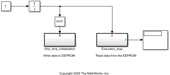
Configure the I2C Controller Write Block
To configure the model to write data to the EEPROM device, open the One_time_initialization subsystem.
open_system("WriteAndReadToI2CEEPROM/One_time_initialization");The subsystem contains an I2C Controller Write block that writes the vector [13 6 87] to the device. To write data to your EEPROM device, double-click the block and set these block parameters:
Set the Board parameter to your Jetson hardware board. In this example, the block uses the
NVIDIA Jetson AGX Xavier Developer Kitsetting.Set the I2C module parameter to the bus that your device is on. In this example, to connect to the
i2c-1bus, set the I2C module parameter to1. The setting for the Board parameter determines the available settings for this parameter.Set the Peripheral address parameter to the address of the EEPROM device. In this example, the device is at the hexadecimal address
74.To write to register
1of the device, set the Peripheral register address parameter. Because the AT24C04C EEPROM in this example uses one byte for addresses, set the register address to1. For a device that uses two-byte addresses, set the register address to[0 1].To transmit the data in the big-endian format, set the Peripheral byte order parameter to
BigEndian. If your device uses little-endian format, set the parameter toLittleEndian.
Alternatively, use this code to set the I2C Controller Write block parameters:
writeBlockName = "WriteAndReadToI2CEEPROM/One_time_initialization/I2C Controller Write";
set_param(writeBlockName,Board="NVIDIA Jetson AGX Xavier Developer Kit");
set_param(writeBlockName,I2CModule_1_8="1");
set_param(writeBlockName,SubAddress="0x74");
set_param(writeBlockName,RegisterAddress="1");
set_param(writeBlockName,SubByteOrder="BigEndian")
Configure the I2C Controller Read Block
The Execution_loop subsystem contains an I2C Controller Read block that reads data from the same EEPROM register. To verify the read configuration, open the subsystem.
open_system("WriteAndReadToI2CEEPROM/Execution_loop");To read the data that the model writes to the board, set the I2C Controller Read block parameters to match the parameters in the I2C Controller Write block:
Set the Board parameter to your hardware board. This example uses the
NVIDIA Jetson AGX Xavier Developer Kitsetting.Set the I2C module parameter to module
1.Set the Peripheral address parameter to
0x74.Set the Peripheral register address parameter to
1.Set the Peripheral byte order parameter to match the byte order of the peripheral device.
To read three bytes from the device, set the Data size (N) parameter to
3.
Alternatively, use this code to set the I2C Controller Read block parameters:
readBlockName = "WriteAndReadToI2CEEPROM/Execution_loop/I2C Controller Read";
set_param(readBlockName,Board="NVIDIA Jetson AGX Xavier Developer Kit");
set_param(readBlockName,I2CModule_1_8="1");
set_param(readBlockName,SubAddress="0x74");
set_param(readBlockName,RegisterAddress="1");
set_param(readBlockName,SubByteOrder="BigEndian")
set_param(readBlockName,DataLength="3")
Deploy and Verify Results from the Model
To run the model on NVIDIA Jetson hardware, on the Simulink Toolstrip, in the Hardware tab, click Monitor & Tune. Simulink generates code, deploys it to the Jetson board, and establishes an external mode connection.
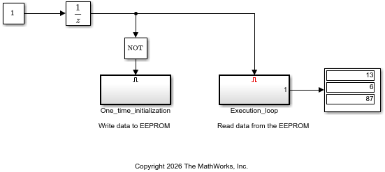
The Display block updates as the model runs and shows that the Jetson hardware reads the data [13 6 87] from the EEPROM.