gsmFrame
Create GSM waveform
Description
gsmWaveform = gsmFrame(gsmCfg)
gsmWaveform = gsmFrame(gsmCfg,numFrames)numFrames identically configured TDMA
frames. In each frame, the encrypted bit field of the transmission data bursts is filled
with random data. For more information, see GSM Frames, Time Slots, and Bursts.
Examples
Create a GSM uplink TDMA frame configuration object with default settings, and then create a GSM waveform containing one TDMA frame. GSM TDMA frames have eight time slots, each separated by a guard period of 8.25 symbols or about 30.46x10e-3 ms. Plot the GSM waveform.
Create a GSM uplink TDMA frame configuration object with default settings.
cfggsmul = gsmUplinkConfig
cfggsmul =
  gsmUplinkConfig with properties:

           BurstType: [NB    NB    NB    NB    NB    NB    NB    NB]
    SamplesPerSymbol: 16
                 TSC: [0 1 2 3 4 5 6 7]
         Attenuation: [0 0 0 0 0 0 0 0]
         PulseLength: 4
            RiseTime: 2
           RiseDelay: 0
            FallTime: 2
           FallDelay: 0
Display information about the configured gsmUplinkConfig object by using the gsmInfo function. Assign the sample rate to a variable, Rs, for use in computing the plot timescale.
wfInfo = gsmInfo(cfggsmul)
wfInfo = struct with fields:
              SymbolRate: 2.7083e+05
              SampleRate: 4.3333e+06
    BandwidthTimeProduct: 0.3000
    BurstLengthInSymbols: 156.2500
       NumBurstsPerFrame: 8
    BurstLengthInSamples: 2500
    FrameLengthInSamples: 20000
Rs = wfInfo.SampleRate;
Create the GSM waveform by using the gsmFrame function, and then plot the GSM waveform.
waveform = gsmFrame(cfggsmul);

t = (0:length(waveform)-1)/Rs*1e3;
subplot(2,1,1)
plot(t,abs(waveform))
grid on
axis([0 5 0 1.2])
title('GSM Uplink Waveform - Amplitude')
xlabel('Time (ms)')
ylabel('Amplitude')
subplot(2,1,2)
plot(t,unwrap(angle(waveform)))
grid on
title('GSM Uplink Waveform - Phase')
xlabel('Time (ms)')
ylabel('Phase (rad)')

Create a GSM downlink TDMA frame configuration object with default settings, and then create a GSM waveform containing five TDMA frames. GSM TDMA frames have eight time slots, each separated by a guard period of 8.25 symbols or about 30.46x10e-3 ms. Plot the GSM waveform.
Create a GSM uplink TDMA frame configuration object, specifying 3 dB of attenuation in the last time slot to help identify the end of each frame.
cfggsmul = gsmUplinkConfig('Attenuation',[0 0 0 0 0 0 0 3])cfggsmul =
gsmUplinkConfig with properties:
BurstType: [NB NB NB NB NB NB NB NB]
SamplesPerSymbol: 16
TSC: [0 1 2 3 4 5 6 7]
Attenuation: [0 0 0 0 0 0 0 3]
PulseLength: 4
RiseTime: 2
RiseDelay: 0
FallTime: 2
FallDelay: 0
Display information about the configured gsmUplinkConfig object by using the gsmInfo function. Assign the frame length in samples to a variable, spf, for use in computing the plot timescale.
wfInfo = gsmInfo(cfggsmul)
wfInfo = struct with fields:
              SymbolRate: 2.7083e+05
              SampleRate: 4.3333e+06
    BandwidthTimeProduct: 0.3000
    BurstLengthInSymbols: 156.2500
       NumBurstsPerFrame: 8
    BurstLengthInSamples: 2500
    FrameLengthInSamples: 20000
spf = wfInfo.FrameLengthInSamples;
Create the GSM waveform by using the gsmFrame function, and then plot the GSM waveform. The last time slot of each frame is 3 dB less than the other time slots in that frame.
numFrames = 5;
waveform = gsmFrame(cfggsmul,numFrames);

t = 8*(0:length(waveform)-1)/spf;

numTS = 8*numFrames;
subplot(2,1,1)
plot(t,abs(waveform))
grid on
axis([0 numTS 0 1.2])
title('GSM Uplink Waveform - Amplitude')
xlabel('Time Slots')
ylabel('Amplitude')
subplot(2,1,2)
plot(t,unwrap(angle(waveform)))
grid on
title('GSM Uplink Waveform - Phase')
xlabel('Time Slots')
ylabel('Phase (rad)')

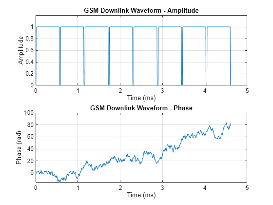
Create a GSM downlink TDMA frame configuration object with default settings, and then create a GSM waveform containing one TDMA frame. The GSM TDMA frame has eight time slots, each separated by a guard period of 8.25 symbols or about 30.46x10e-3 ms. Plot the GSM waveform.
Create a GSM downlink TDMA frame configuration object with default settings.
cfggsmdl = gsmDownlinkConfig
cfggsmdl =
  gsmDownlinkConfig with properties:

           BurstType: [NB    NB    NB    NB    NB    NB    NB    NB]
    SamplesPerSymbol: 16
                 TSC: [0 1 2 3 4 5 6 7]
         Attenuation: [0 0 0 0 0 0 0 0]
         PulseLength: 4
            RiseTime: 2
           RiseDelay: 0
            FallTime: 2
           FallDelay: 0
Display information about the configured gsmDownlinkConfig object by using the gsmInfo function. Assign the sample rate to a variable, Rs, for use in computing the plot timescale.
wfInfo = gsmInfo(cfggsmdl)
wfInfo = struct with fields:
              SymbolRate: 2.7083e+05
              SampleRate: 4.3333e+06
    BandwidthTimeProduct: 0.3000
    BurstLengthInSymbols: 156.2500
       NumBurstsPerFrame: 8
    BurstLengthInSamples: 2500
    FrameLengthInSamples: 20000
Rs = wfInfo.SampleRate;
Create the GSM waveform by using the gsmFrame function, and then plot the GSM waveform.
waveform = gsmFrame(cfggsmdl);

t = (0:length(waveform)-1)/Rs*1e3;
subplot(2,1,1)
plot(t,abs(waveform))
grid on
axis([0 5 0 1.2])
title('GSM Downlink Waveform - Amplitude')
xlabel('Time (ms)')
ylabel('Amplitude')
subplot(2,1,2)
plot(t,unwrap(angle(waveform)))
grid on
title('GSM Downlink Waveform - Phase')
xlabel('Time (ms)')
ylabel('Phase (rad)')

Input Arguments
GSM configuration, specified as a gsmUplinkConfig
or gsmDownlinkConfig object.
Number of TDMA frames in the waveform, specified as a positive integer.
Data Types: double
Output Arguments
Output time-domain waveform, returned as a complex-valued column vector of length Ns, where Ns represents the number of time-domain samples. The function generates this waveform in the form of complex in-phase quadrature (IQ) samples.
More About
In GSM, transmissions consist of TDMA frames. Each GSM TDMA frame consists of eight time slots. The transmission data content of a time slot is called a burst. As described in Section 5.2 of 3GPP TS 45.011, a GSM time slot has a 156.25-symbol duration when using the normal symbol period, which is a time interval of 15/26 ms or about 576.9 microseconds. A guard period of 8.25 symbols or about 30.46 microseconds separates each time slot. The GSM standards describes a symbol as one bit period. Since GSM uses GMSK modulation, there is one bit per bit period. The transmission timing of a burst within a time slot is defined in terms of the bit number (BN). The BN refers to a particular bit period within a time slot. The bit with the lowest BN is transmitted first. BN0 is the first bit period, and BN156 is the last quarter-bit period.
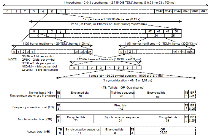
This image from 3GPP TS 45.011 shows the relationship between different frame types and the relationship between different burst types.

This table shows the supported burst types and their characteristics.
| Burst Type | Description | Link Direction | Useful Duration |
|---|---|---|---|
NB | Normal burst | Uplink/Downlink | 147 |
FB | Frequency correction burst | Downlink | 147 |
SB | Synchronization burst | Downlink | 147 |
Dummy | Dummy burst | Downlink | 147 |
AB | Access burst | Uplink | 87 |
Off | No burst sent | Uplink/Downlink | 0 |
Useful duration, described in Section 5.2.2 of 3GPP TS 45.002, is a characteristic of GSM bursts. The useful duration, or useful part, of a burst is defined as beginning halfway through BN0 and ending half a bit period before the start of the guard period. The guard period is the period between bursts in successive time slots. This figure, from Section 2.2 of 3GPP TS 45.004, shows the leading and trailing ½ bit difference between the useful and active parts of the burst.

For more information, see GSM TDMA Frame Parameterization for Waveform Generation.
Normal bursts include a training sequence bits field assigned a bit pattern based on the specified TSC. For GSM, you can select one of these eight training sequences for normal burst type time slots.
Training Sequence Code (TSC) | Training Sequence Bits (BN61, BN62, …, BN86) |
|---|---|
0 | (0,0,1,0,0,1,0,1,1,1,0,0,0,0,1,0,0,0,1,0,0,1,0,1,1,1) |
1 | (0,0,1,0,1,1,0,1,1,1,0,1,1,1,1,0,0,0,1,0,1,1,0,1,1,1) |
2 | (0,1,0,0,0,0,1,1,1,0,1,1,1,0,1,0,0,1,0,0,0,0,1,1,1,0) |
3 | (0,1,0,0,0,1,1,1,1,0,1,1,0,1,0,0,0,1,0,0,0,1,1,1,1,0) |
4 | (0,0,0,1,1,0,1,0,1,1,1,0,0,1,0,0,0,0,0,1,1,0,1,0,1,1) |
5 | (0,1,0,0,1,1,1,0,1,0,1,1,0,0,0,0,0,1,0,0,1,1,1,0,1,0) |
6 | (1,0,1,0,0,1,1,1,1,1,0,1,1,0,0,0,1,0,1,0,0,1,1,1,1,1) |
7 | (1,1,1,0,1,1,1,1,0,0,0,1,0,0,1,0,1,1,1,0,1,1,1,1,0,0) |
For more information, see Section 5.2.3 in 3GPP TS 45.002.
Extended Capabilities
C/C++ Code Generation
Generate C and C++ code using MATLAB® Coder™.
Version History
Introduced in R2019bThis update allows you to optimize the spectral occupancy of your design by selecting
the pulse length. When generating downlink and uplink GSM frames with the
gsmFrame function, you can specify the pulse length in the GMSK
modulator for the Gaussian filter with the gsmDownlinkConfig
and gsmUplinkConfig
configuration objects by setting the PulseLength property. The default
value sets pulse length to 4. The gsmFrame
function now also implements raised cosine roll-off instead of sine roll-off for the
spectral shape of the rise and fall mask.
Previous releases used a static pulse length of 1 in the GMSK modulator and sine-shaped spectral rise and fall masks. The raised cosine roll-off shape and pulse length of 4, improves the out-of-channel and out-of-band spectral rejection.
See Also
Objects
Functions
MATLAB Command
You clicked a link that corresponds to this MATLAB command:
Run the command by entering it in the MATLAB Command Window. Web browsers do not support MATLAB commands.
Select a Web Site
Choose a web site to get translated content where available and see local events and offers. Based on your location, we recommend that you select: .
You can also select a web site from the following list
How to Get Best Site Performance
Select the China site (in Chinese or English) for best site performance. Other MathWorks country sites are not optimized for visits from your location.
Americas
- América Latina (Español)
- Canada (English)
- United States (English)
Europe
- Belgium (English)
- Denmark (English)
- Deutschland (Deutsch)
- España (Español)
- Finland (English)
- France (Français)
- Ireland (English)
- Italia (Italiano)
- Luxembourg (English)
- Netherlands (English)
- Norway (English)
- Österreich (Deutsch)
- Portugal (English)
- Sweden (English)
- Switzerland
- United Kingdom (English)