Accelerate Simulation Using GPUs
R2026bYou can design your MATLAB® simulation by using functions or System objects that support GPU-based processing. You can also build your Simulink® model by using MATLAB System (Simulink) blocks that include GPU-based System objects in them. GPUs excel at processing large quantities of data and performing computations with high compute intensity. Processing large quantities of data is one way to maximize the throughput of your GPU in a simulation. The amount of data that the GPU processes at any one time depends on the size of the data passed to the input of a GPU-based simulation.
Passing MATLAB arrays to a GPU-based simulation requires transferring the initial data from a CPU to the GPU for GPU-based processing. Afterward, the simulation transfers the output data back to the CPU. Repeating this process introduces latency. To increase the speed of your GPU-based simulation, avoid data transfer latency by:
Minimizing the number of data transfers between the CPU and the GPU
Passing data in the form of a
gpuArray(Parallel Computing Toolbox) object to GPU-capable functions and System objects runs faster. For more information, see Establish Arrays on a GPU (Parallel Computing Toolbox).
Pass Data Using gpuArray Input Signal
In this example, you transmit 1/2 rate convolutionally encoded 16-PSK-modulated data through an AWGN channel, demodulate and decode the received data, and assess the error rate of the received data. For this implementation, you use the GPU-based Viterbi decoder System object™ to process multiple signal frames in a single call and use gpuArray (Parallel Computing Toolbox) objects to pass data into and out of the functions and the GPU-based System object.
Create GPU-based System object™ for Viterbi decoding and an error rate calculation System object.
numframes = 100;
gpuvitdec = comm.gpu.ViterbiDecoder( ...
    InputFormat='Hard', ...
    TerminationMethod='Truncated', ...
    NumFrames=numframes);
errorrate = comm.ErrorRate(ComputationDelay=0,ReceiveDelay=0);
Due to the computational complexity of the Viterbi decoding algorithm, loading multiple frames of signal data on the GPU and processing them in one call can reduce overall simulation time. To enable this implementation, the GPU-based Viterbi decoder System object contains a NumFrames property. Instead of using an external for-loop to process individual frames of data, you use the NumFrames property to configure the GPU-based Viterbi decoder System object to process multiple data frames. Generate numframes of binary data frames. To efficiently manage the data frames for processing, represent the transmission data frames as a gpuArray object.
numsymbols = 50;
rate = 1/2;
M = 16; % Modulation order
dataA = gpuArray.randi([0 1],rate*numsymbols*log2(M),numframes);
Perform the GPU-based encoding, modulation, AWGN, and demodulation inside a for-loop.
demodsig = zeros(numsymbols*log2(M),numframes);
for ii = 1:numframes
    encodedData = convenc(dataA(:,ii),poly2trellis(7,[171,133]));
    modsig = pskmod(encodedData,M,pi/16,InputType="bit");
    noisysig = awgn(modsig,15); % SNR=15 dB. Signal power=0 dBW
    demodsig(:,ii) = pskdemod(noisysig,M,pi/16,OutputType="bit");
end
The GPU-based Viterbi decoder performs multiframe processing without a for-loop.
rxbits = gpuvitdec(demodsig(:));
The error rate object does not support gpuArray objects or multichannel data, so you must retrieve the array from the GPU by using the gather (Parallel Computing Toolbox) function to compute the error rate on each frame of data.
errorStats = errorrate(gather(dataA(:)),gather(rxbits));
fprintf('BER = %f\nNumber of errors = %d\nTotal bits = %d', ...
    errorStats(1), errorStats(2), errorStats(3))
BER = 0.001000
Number of errors = 10
Total bits = 10000
LDPC Decoding Using GPU
Use a GPU to accelerate LDPC encoding, PSK modulation, AWGN channel modeling, PSK demodulation, LDPC decoding, and bit error rate computation. In this example you compute the error statistics for the belief propagation decoding algorithm and the normalized min-sum decoding algorithm.
Create LDPC Configuration Objects
Create an LDPC encoder configuration object and an LDPC decoder configuration object. Define simulation variables.
% Use ldpcQuasiCyclicMatrix to create a parity-check matrix
load("LDPCExamplePrototypeMatrix.mat","P"); % A prototype matrix from the 5G standard
blockSize = 384;
H = ldpcQuasiCyclicMatrix(blockSize, P);
encoderCfg = ldpcEncoderConfig(H);
decoderCfg1 = ldpcDecoderConfig(encoderCfg); % The default algorithm is "bp"
decoderCfg2 = ldpcDecoderConfig(encoderCfg,"norm-min-sum");

M = 4; % Modulation order (QPSK)
snr = [-2 -1.5 -1];
numFramesPerCall = 50;
numCalls = 40;
maxNumIter = 20;
s = rng(1235); % Fix random seed
errRate = zeros(length(snr),2);
Compute Bit Error Rates
Generate random bits in a gpuArray (Parallel Computing Toolbox) object and let its data flow through the ldpcEncode, pskmod, awgn, pskdemod, ldpcDecode, and biterr functions. For each SNR setting, compute the error statistics for the belief propagation decoding algorithm and the normalized min-sum decoding algorithm.
for ii = 1:length(snr)
    ttlErr = [0 0];
    noiseVariance = 1/10^(snr(ii)/10);
    for counter = 1:numCalls
        data = gpuArray.randi([0 1],encoderCfg.NumInformationBits,numFramesPerCall,'logical');

        % Transmit and receive LDPC coded signal data
        encData = ldpcEncode(data,encoderCfg);
        modSig = pskmod(encData,M,pi/4,'InputType','bit');
        rxSig = awgn(modSig,snr(ii)); % Signal power = 0 dBW
        demodSig = pskdemod(rxSig,M,pi/4,...
            'OutputType','approxllr','NoiseVariance',noiseVariance);

        % Decode and update number of bit errors

        % Using bp
        rxBits1 = ldpcDecode(demodSig,decoderCfg1,maxNumIter);
        numErr1 = biterr(data,rxBits1);

        % Using norm-min-sum
        rxBits2 = ldpcDecode(demodSig,decoderCfg2,maxNumIter);
        numErr2 = biterr(data,rxBits2);

        ttlErr = ttlErr + [numErr1 numErr2];
    end
    ttlBits = numCalls*numel(rxBits1);

    errRate(ii,:) = ttlErr/ttlBits;
end
Compare Bit Error Rates
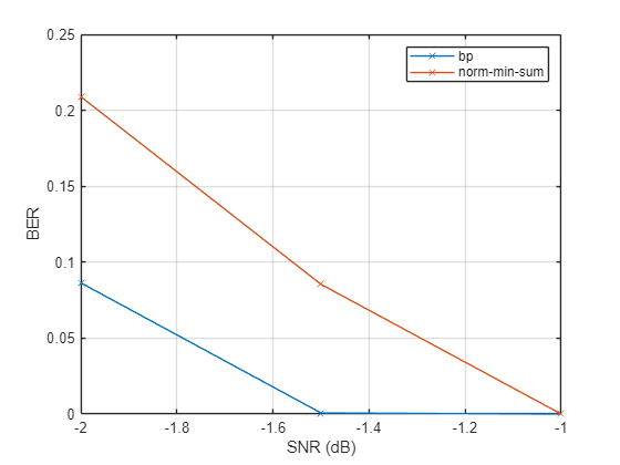
Plot the error statistics. The belief propagation algorithm is expected to achieve a slightly lower bit error rate than the normalized min-sum algorithm.
plot(snr,errRate,'-x')
grid on
legend('bp','norm-min-sum')
xlabel('SNR (dB)')
ylabel('BER')
Compare Speeds
Compare the execution speeds of four cases. By default, ldpcDecode terminates decoding when all parity checks are satisfied.
% Use belief propagation algorithm on CPU, without multithreading
demodSigCPU = gather(demodSig);
tic
[rxBitsCPU1,actualNumIterCPU1,finalParityChecksCPU1] = ...
    ldpcDecode(demodSigCPU,decoderCfg1,maxNumIter,'Multithreaded',false);
toc
Elapsed time is 4.270400 seconds.
% Use belief propagation algorithm on CPU, with multithreading
tic
[rxBitsCPU2,actualNumIterCPU2,finalParityChecksCPU2] = ...
    ldpcDecode(demodSigCPU,decoderCfg1,maxNumIter);
toc
Elapsed time is 1.069500 seconds.
% Use belief propagation algorithm on GPU
tic
[rxBits1,actualNumIter1,finalParityChecks1] = ...
    ldpcDecode(demodSig,decoderCfg1,maxNumIter);
toc
Elapsed time is 2.117112 seconds.
% Use normalized min-sum algorithm on GPU
tic
[rxBits2,actualNumIter2,finalParityChecks2] = ...
    ldpcDecode(demodSig,decoderCfg2,maxNumIter);
toc
Elapsed time is 0.615488 seconds.
Examine Optional Decoder Outputs
Confirm that the normalized min-sum algorithm needs fewer iterations than the belief propagation algorithm when the SNR is sufficiently high.
length(find(actualNumIter2 < actualNumIter1))
ans =
50
length(find(actualNumIter2 == actualNumIter1))
ans =
0
Confirm that the final parity checks are all zeros when the actual number of iterations executed is less than the maximum number of iterations specified.
nnz(finalParityChecks1(:,actualNumIter1<maxNumIter))
ans =
0
nnz(finalParityChecks2(:,actualNumIter2<maxNumIter))
ans =
0
Restore the state for random number generation.
rng(s);
Generate Random Numbers Using CPU and GPU
To compare results, validate the implementation, and ensure reproducibility for simulations runs on CPUs and GPUs, you must add the exact same noise to the CPU and GPU simulation runs. Producing the same sequence of random numbers with CPU and GPU requires that you adjust the default random stream inputs as shown in this example.
To set random number generation:
Compare Default Random Number Generation in CPU and GPU
Compare random numbers generated on CPU and GPU to show the default settings do not produce the same sequences.
RNG sequence from CPU:
rng(0,'threefry')
disp(randn(5,1,like=1i))
-0.2460 + 0.0747i 0.2807 + 0.4627i -1.2889 + 0.6779i 0.3790 - 0.4087i -0.8439 + 0.1195i
RNG sequence from GPU:
gpurng(0,'threefry')
disp(randn(5,1,like=gpuArray(1i)))
-0.9704 - 0.2627i -0.0263 - 0.6508i 0.8967 - 1.6039i -0.1171 + 0.5807i -1.3383 - 0.6001i
Configure to Generate Same Sequence of Random Numbers in CPU and GPU
To generate the same sequence of random numbers on both CPU and GPU, configure use the RandStream and parallel.gpu.RandStream (Parallel Computing Toolbox) objects to use the "combRecursive" generator with the NormalTransform property set to "Inversion". After you configure the random stream properly, the CPU and the GPU generate the same sequence of random numbers.
RNG sequence from CPU:
sC = RandStream("combRecursive",NormalTransform="Inversion");
RandStream.setGlobalStream(sC)
randn(5,1,like=1i)
ans = 5×1 complex

     0.4270 - 0.0850i
     1.0918 - 0.5085i
    -1.3548 - 0.7912i
    -0.5672 + 1.0563i
    -0.3340 - 0.3248i
RNG sequence from GPU:
sG = parallel.gpu.RandStream("combRecursive",NormalTransform="Inversion");
parallel.gpu.RandStream.setGlobalStream(sG)
disp(randn(5,1,like=gpuArray(1i)))
   0.4270 - 0.0850i
   1.0918 - 0.5085i
  -1.3548 - 0.7912i
  -0.5672 + 1.0563i
  -0.3340 - 0.3248i
Communications system simulations use random numbers to model effects such as data, noise, fading channels, interference, and more. For example, to simulate the effect of thermal noise in a communications system, the comm.ThermalNoise System object adds random noise to a signal generated. The comm.ThermalNoise object uses the random stream object to generate random thermal noise values. Use comm.ThermalNoise to generate the same sequence of random numbers on both the CPU and GPU.
Thermal noise added when run on the CPU:
tncpu = comm.ThermalNoise;
format long
sC = RandStream("combRecursive",NormalTransform="Inversion");
RandStream.setGlobalStream(sC)
disp(tncpu(ones(5,1)+1i))
  1.000000000027016 + 0.999999999994624i
  1.000000000069087 + 0.999999999967825i
  0.999999999914274 + 0.999999999949935i
  0.999999999964107 + 1.000000000066840i
  0.999999999978868 + 0.999999999979446i
Thermal noise added when run on the GPU:
tngpu = comm.ThermalNoise;
sG = parallel.gpu.RandStream("combRecursive",NormalTransform="Inversion")
sG =
mrg32k3a random stream on the GPU
             Seed: 0
  NormalTransform: Inversion
parallel.gpu.RandStream.setGlobalStream(sG)
tngpu(gpuArray(ones(5,1)+1i))
ans =

  1.000000000027016 + 0.999999999994624i
  1.000000000069087 + 0.999999999967825i
  0.999999999914274 + 0.999999999949935i
  0.999999999964107 + 1.000000000066840i
  0.999999999978868 + 0.999999999979446i
See Also
Topics
- Accelerate Ray Tracing Analysis Using GPU
- Accelerate MIMO-OFDM Link Simulation Using GPU
- Accelerate SISO Single-Carrier Link Simulation Using GPU
- Run MATLAB Functions on a GPU (Parallel Computing Toolbox)
- GPU Computing Requirements (Parallel Computing Toolbox)
- C/C++ Code Generation

