Visualize Sensor Data and Tracks in Bird's-Eye Scope
The Bird's-Eye Scope visualizes signals from your Simulink® model that represent aspects of a driving scenario. Using the scope, you can analyze:
Sensor coverages of vision, radar, and lidar sensors
Sensor detections of actors and lane boundaries
Tracks of moving objects in the scenario
This example shows you how to display these signals on the scope and analyze the signals during simulation.
Open Model and Scope
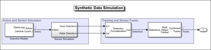
Open a model containing signals for sensor detections and tracks. This model is used in the Sensor Fusion Using Synthetic Radar and Vision Data in Simulink example. Open the example model in MATLAB®.
openExample('driving/SensorFusionUsingSyntheticRadarAndVisionDataExample')
Open the scope from the Simulink toolstrip. Under Review Results, click Bird's-Eye Scope.
Find Signals
When you first open the Bird's-Eye Scope, the scope canvas is blank and displays no signals. To find signals from the opened model that the scope can display, on the scope toolstrip, click Find Signals. The scope updates the block diagram and automatically finds the signals in the model.
The left pane lists all the signals that the scope found. These signals are grouped based on their sources within the model.
| Signal Group | Description | Signal Sources |
|---|---|---|
| Ground Truth | Road boundaries, lane markings and barriers in the scenario You cannot modify this group or any of its signals. To inspect large road networks, use the World Coordinates View window. See Vehicle and World Coordinate Views. |
|
| Actors | Actors in the scenario, including the ego vehicle You cannot modify this group or any of its signals or subgroups. To view actors that are located away from the ego vehicle, use the World Coordinates View window. See Vehicle and World Coordinate Views. |
|
| Sensor Coverage | Coverage areas of vision, radar, and lidar sensors, sorted into Vision, Radar, Lidar, and Ultrasonic subgroups You can modify signals in this group. You can rename or delete subgroups but not the top-level Sensor Coverage group. You can also add subgroups and move signals between subgroups. If you delete a subgroup, its signals move to the top-level Sensor Coverage group. | |
| Detections | Detections obtained from vision, radar, and lidar sensors, sorted into Vision, Radar, Lidar, and Ultrasonic subgroups You can modify signals in this group. You can rename or delete subgroups but not the top-level Detections group. You can also add subgroups and move signals between subgroups. If you delete a subgroup, its signals move to the top-level Detections group. | |
| Tracks | Tracks of objects in the scenario You can modify signals in this group. You can rename or delete subgroups but not the top-level Tracks group. You can also add subgroups to this group and move signals into them. If you delete a subgroup, its signals move to the top-level Tracks group. |
The Bird's-Eye Scope displays tracks in ego vehicle coordinates. Tracks in any other coordinate system will appear as offset in the scope. |
| Other Applicable Signals | Signals that the scope cannot automatically group, such as ones that combine information from multiple sensors You can modify signals in this group but you cannot add subgroups. Signals in this group do not display during simulation. |
|
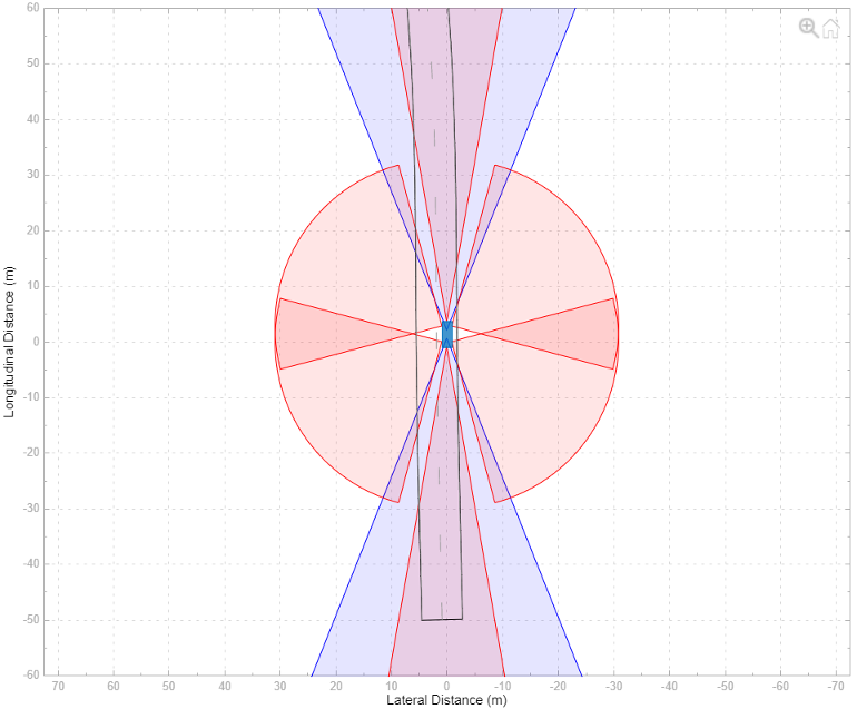
Before simulation but after clicking Find Signals, the scope canvas displays all Ground Truth signals except for non-ego actors and all Sensor Coverage signals. The non-ego actors and the signals under Detections and Tracks do not display until you simulate the model. The signals in Other Applicable Signals do not display during simulation. If you want the scope to display specific signals, move them into the appropriate group before simulation. If an appropriate group does not exist, create one.
Run Simulation
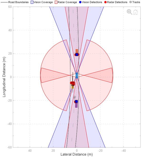
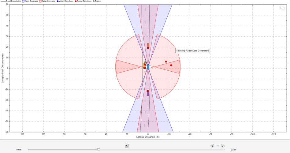
Simulate the model from within the Bird's-Eye Scope by clicking Run. The scope canvas displays the detections and tracks. To display the legend, on the scope toolstrip, click Legend.
During simulation, you can perform these actions:
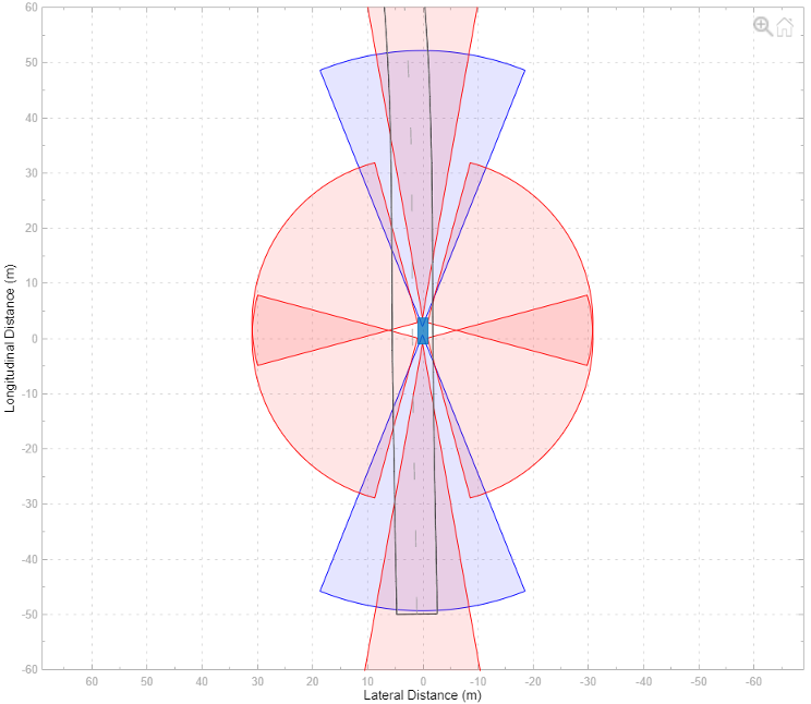
Inspect detections, tracks, sensor coverage areas, and ego vehicle behavior. The default view displays the simulation in vehicle coordinates and is centered on the ego vehicle. To view the wider area around the ego vehicle, or to view other parts of the scenario, on the scope toolstrip, click World Coordinates. The World Coordinates View window displays the entire scenario, with the ego vehicle circled. This circle is not a sensor coverage area. To return to the default display of either window, move your pointer over the window, and in the upper-right corner, click the home button
 that appears. For more details on these
views, see Vehicle and World Coordinate Views.
that appears. For more details on these
views, see Vehicle and World Coordinate Views.Update signal properties. To access the properties of a signal, first select the signal from the left pane. Then, on the scope toolstrip, click Properties. Using these properties, you can, for example, show or hide sensor coverage areas or detections. In addition, to highlight certain sensor coverage areas, you can change their color or transparency.
Update Bird's-Eye Scope settings, such as changing the axes limits of the Vehicle Coordinates View window or changing the display of signal names. On the scope toolstrip, click Settings. You cannot change the Track position selector and Track velocity selector settings during simulation. For more details, see the Settings > Vehicle Coordinates View section of the Bird's-Eye Scope reference page.
After simulation, you can hide certain detections or tracks for the next simulation. In the left pane, under Detections or Tracks, right-click the signal you want to hide. Then, select Move to Other Applicable to move that signal into the Other Applicable Signals group. To hide sensor coverage areas, select the corresponding signal in the left pane, and on the Properties tab, clear the Show Sensor Coverage parameter. You cannot hide Ground Truth signals during simulation.
Organize Signal Groups (Optional)
To further organize the signals, you can rename signal groups or move signals into new groups. For example, you can rename the Vision and Radar subgroups to Front of Car and Back of Car. Then you can drag the signals as needed to move them into the appropriate groups based on the new group names. When you drag a signal to a new group, the color of the signal changes to match the color assigned to its group.
You cannot rename or delete the top-level groups in the left pane, but you can rename or delete any subgroup. If you delete a subgroup, its signals move to the top-level group.
Update Sensor Parameters and Rerun Simulation
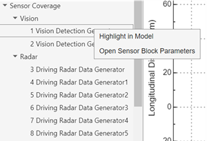
After you run the simulation, modify the sensor parameters and inspect how the changes affect the visualization on the Bird's-Eye Scope. In the left pane, the Sensor Coverage group lists all the sensors in the scenario. You can right click the sensor Vision Detection Generator, and then click Open Sensor Block Parameters.
This opens the sensor parameter dialog. On the Measurements tab,
reduce the Maximum detection range (m) parameter to
50. The app automatically updates the sensor coverage area.
You can also change any other desired sensor parameters and rerun the simulation.
When you modify block parameters, you can rerun the simulation without having to find signals again. If you add or remove blocks, ports, or signal lines, then you must click Find Signals again before rerunning the simulation.
Record and Replay Simulation Run
The Bird's-Eye Scope app always automatically records the current simulation run. When you click Run to run the simulation, the app automatically records all the scenario and sensor data during the simulation.
After the simulation run is complete, you can use the playback controls pane in the bottom of the app to replay the recorded simulation. You can seek to any time step and also adjust the playback speed. You can use the Playback Controls option on the toolstrip to hide/unhide the controls at the bottom.
The app only records one simulation run. If you rerun the simulation, the app overwrites the existing record with the new simulation data.
Save and Close Model
When you save and close the model, the settings for the Bird's-Eye Scope are also saved.
If you reopen the model and the Bird's-Eye Scope, the scope canvas is initially blank. Click Run to run the simulation and visualize the saved signal properties. For example, if you reduced the detection range in the previous step, the scope canvas displays this reduced range.
If you add new signals to the model, click Update Signals to find the new signals, and then click Run to visualize the model with the new signals.
Note
If you did not make a graphical change to the Bird's-Eye Scope before closing the model, then, when you reopen the model, you have to find signals again before running the simulation. Graphical changes include:
Dragging signals to new groups
Enabling the legend or World Coordinates View window
Changing axes limits
Changing the visual properties of actors, lane markings, or sensor coverage areas
See Also
Apps
Blocks
- Detection Concatenation | Vision Detection Generator | Driving Radar Data Generator | Multi-Object Tracker | Scenario Reader | Simulation 3D Lidar | Simulation 3D Probabilistic Radar | Lidar Point Cloud Generator
Topics
- Visualize Sensor Data from Unreal Engine Simulation Environment
- Sensor Fusion Using Synthetic Radar and Vision Data in Simulink
- Lateral Control Tutorial
- Autonomous Emergency Braking with Sensor Fusion
- Test Open-Loop ADAS Algorithm Using Driving Scenario
- Test Closed-Loop ADAS Algorithm Using Driving Scenario