Main Content

dsp.LowpassFilter

FIR or IIR lowpass filter

Description

The dsp.LowpassFilter object independently filters each channel of the input over time using the given design specifications. You can set the FilterType property to 'FIR' or 'IIR' to implement the object as an FIR or an IIR lowpass filter.

When the FilterType property is set to 'FIR', using this object is an alternative to using the firceqrip and firgr functions with dsp.FIRFilter. The dsp.LowpassFilter object condenses the two-step process into one. You can use measure to verify that the design meets the prescribed specifications.

To filter each channel of your input:

  1. Create the dsp.LowpassFilter object and set its properties.

  2. Call the object with arguments, as if it were a function.

To learn more about how System objects work, see What Are System Objects?

This object supports C/C++ code generation and SIMD code generation under certain conditions. This object also supports code generation for ARM® Cortex®-M and ARM Cortex-A processors. For more information, see Code Generation.

Creation

Description

LPF = dsp.LowpassFilter returns a minimum order FIR lowpass filter with the default filter settings. Calling the object with the default property settings filters the input data with a passband frequency of 8 kHz, a stopband frequency of 12 kHz, a passband ripple of 0.1 dB, and a stopband attenuation of 80 dB.

example

LPF = dsp.LowpassFilter(Name=Value) returns a lowpass filter with additional properties specified by one or more Name-Value pair arguments. Name is the property name and Value is the corresponding value. For example, PassbandFrequency=8000 sets the passband frequency specification of the filter to 8000 Hz.

Properties

expand all

Unless otherwise indicated, properties are nontunable, which means you cannot change their values after calling the object. Objects lock when you call them, and the release function unlocks them.

If a property is tunable, you can change its value at any time.

For more information on changing property values, see System Design in MATLAB Using System Objects.

Type of filter response, specified as one of these options:

  • 'FIR' — The object designs an FIR lowpass filter.

  • 'IIR' — The object designs an IIR lowpass (biquad) filter.

Flag to design minimum order filter, specified as:

  • true –– The object designs the minimum order filter that meets the filter design specifications.

  • false –– The object designs the filter with the order that you specify in the FilterOrder property.

Order of the FIR or IIR filter, specified as a positive integer.

Dependencies

To enable this property, set DesignForMinimumOrder to false.

Data Types: single | double | int8 | int16 | int32 | int64 | uint8 | uint16 | uint32 | uint64

Filter passband edge frequency, specified as a real positive scalar in Hz or in normalized frequency units (since R2023a).

If you set the NormalizedFrequency property to:

  • false –– The value of the passband edge frequency is in Hz and must be less than the stopband frequency and half the SampleRate property value.

  • true –– The value of the passband edge frequency is in normalized frequency units. The value must be a positive scalar less than 1.0.

(since R2023a)

Data Types: single | double | int8 | int16 | int32 | int64 | uint8 | uint16 | uint32 | uint64

Filter stopband edge frequency, specified as a real positive scalar in Hz or in normalized frequency units (since R2023a).

If you set the NormalizedFrequency property to:

  • false –– The value of the stopband edge frequency is in Hz. The value must be greater than the passband edge frequency and less than half the SampleRate property value.

  • true –– The value of the stopband edge frequency is in normalized frequency units. The value must be a positive scalar greater than the passband edge frequency and less than 1.0.

(since R2023a)

Dependencies

To enable this property, set the DesignForMinimumOrder property to true.

Data Types: single | double | int8 | int16 | int32 | int64 | uint8 | uint16 | uint32 | uint64

Maximum ripple of filter response in the passband, specified as a real positive scalar in dB.

Data Types: single | double | int8 | int16 | int32 | int64 | uint8 | uint16 | uint32 | uint64

Minimum attenuation in the stopband, specified as a real positive scalar in dB.

Data Types: single | double | int8 | int16 | int32 | int64 | uint8 | uint16 | uint32 | uint64

Since R2023a

Flag to set frequencies in normalized units, specified as one of these values:

  • true –– The passband edge and stopband edge frequencies must be in the normalized frequency units and less than 1.0.

  • false –– The passband edge and stopband edge frequencies are in Hz. You can specify the input sample rate through the SampleRate property.

Data Types: logical

Input sample rate in Hz, specified as a real positive scalar.

Dependency

To enable this property, set NormalizedFrequency to false. (since R2023a)

Data Types: single | double

Fixed-Point Properties

Rounding method for output fixed-point operations, specified as a character vector. For more information on the rounding modes, see Precision and Range.

Word and fraction lengths of coefficients, specified as a numerictype object. The default, numerictype(1,16) corresponds to a signed numeric type object with 16-bit coefficients and a fraction length determined based on the coefficient values, to give the best possible precision.

This property is not tunable.

Word length of the output is same as the word length of the input. Fraction length of the output is computed such that the entire dynamic range of the output can be represented without overflow. For details on how the fraction length of the output is computed, see Fixed-Point Precision Rules for Avoiding Overflow in FIR Filters.

Usage

Description

example

y = LPF(x) lowpass filters the input signal, x. y is a lowpass-filtered version of x.

Input Arguments

expand all

Noisy data input, specified as a vector or a matrix. If the input signal is a matrix, each column of the matrix is treated as an independent channel. The number of rows in the input signal denote the channel length. This object accepts variable-size inputs. After the object is locked, you can change the size of each input channel, but you cannot change the number of channels.

Data Types: single | double | int8 | int16 | int32 | int64 | uint8 | uint16 | uint32 | uint64 | fi
Complex Number Support: Yes

Output Arguments

expand all

Filtered output, returned as a vector or a matrix. The output has the same size, data type, and complexity characteristics as the input.

Data Types: single | double | int8 | int16 | int32 | int64 | uint8 | uint16 | uint32 | uint64 | fi
Complex Number Support: Yes

Object Functions

To use an object function, specify the System object™ as the first input argument. For example, to release system resources of a System object named obj, use this syntax:

release(obj)

expand all

freqzFrequency response of discrete-time filter System object
fvtoolVisualize frequency response of DSP filters
impzImpulse response of discrete-time filter System object
infoInformation about filter System object
coeffsReturns the filter System object coefficients in a structure
costEstimate cost of implementing filter System object
grpdelayGroup delay response of discrete-time filter System object
generatehdlGenerate HDL code for quantized DSP filter (requires Filter Design HDL Coder)
measureMeasure frequency response characteristics of filter System object
outputDelayDetermine output delay of single-rate or multirate filter
stepRun System object algorithm
releaseRelease resources and allow changes to System object property values and input characteristics
resetReset internal states of System object

Examples

collapse all

Create a minimum-order FIR lowpass filter for data sampled at 44.1 kHz. Specify a passband frequency of 8 kHz, a stopband frequency of 12 kHz, a passband ripple of 0.1 dB, and a stopband attenuation of 80 dB.

Fs = 44.1e3; 
filtertype = 'FIR';
Fpass = 8e3;
Fstop = 12e3; 
Rp = 0.1;
Astop = 80;
FIRLPF = dsp.LowpassFilter(SampleRate=Fs,...
                             FilterType=filtertype,...
                             PassbandFrequency=Fpass,...
                             StopbandFrequency=Fstop,...
                             PassbandRipple=Rp,...
                             StopbandAttenuation=Astop);

Design a minimum-order IIR lowpass filter with the same properties as the FIR lowpass filter. Change the FilterType property of the cloned filter to IIR.

IIRLPF = clone(FIRLPF);
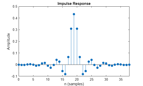
IIRLPF.FilterType = 'IIR';

Plot the impulse response of the FIR lowpass filter. The zeroth-order coefficient is delayed by 19 samples, which is equal to the group delay of the filter. The FIR lowpass filter is a causal FIR filter.

fvtool(FIRLPF,Analysis='impulse')

Figure Figure 1: Impulse Response contains an axes object. The axes object with title Impulse Response, xlabel Time (us), ylabel Amplitude contains an object of type stem.

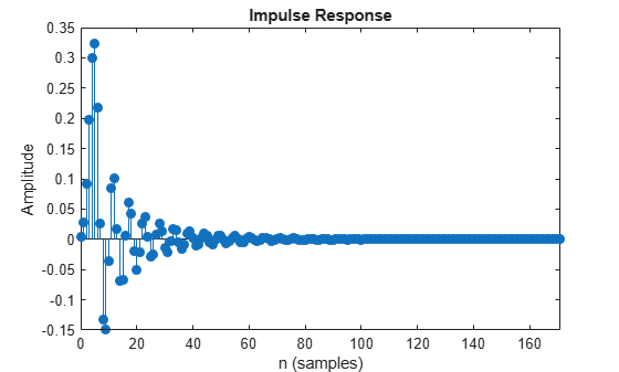
Plot the impulse response of the IIR lowpass filter.

fvtool(IIRLPF,Analysis='impulse')

Figure Figure 2: Impulse Response contains an axes object. The axes object with title Impulse Response, xlabel Time (ms), ylabel Amplitude contains an object of type stem.

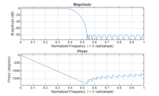
Plot the magnitude and phase response of the FIR lowpass filter.

fvtool(FIRLPF,Analysis='freq')

Figure Figure 3: Magnitude Response (dB) and Phase Response contains an axes object. The axes object with title Magnitude Response (dB) and Phase Response, xlabel Frequency (kHz), ylabel Magnitude (dB) contains an object of type line.

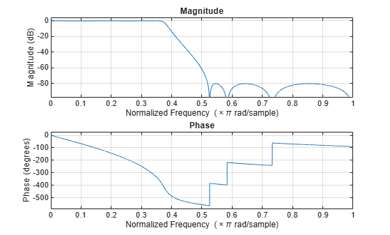
Plot the magnitude and phase response of the IIR lowpass filter.

fvtool(IIRLPF,Analysis='freq')

Figure Figure 4: Magnitude Response (dB) and Phase Response contains an axes object. The axes object with title Magnitude Response (dB) and Phase Response, xlabel Frequency (kHz), ylabel Magnitude (dB) contains an object of type line.

Calculate the cost of implementing the FIR lowpass filter.

cost(FIRLPF)
ans = struct with fields:
                  NumCoefficients: 39
                        NumStates: 38
    MultiplicationsPerInputSample: 39
          AdditionsPerInputSample: 38

Calculate the cost of implementing the IIR lowpass filter. The IIR filter is more efficient to implement than the FIR filter.

cost(IIRLPF)
ans = struct with fields:
                  NumCoefficients: 18
                        NumStates: 14
    MultiplicationsPerInputSample: 18
          AdditionsPerInputSample: 14

Calculate the group delay of the FIR lowpass filter.

grpdelay(FIRLPF)

Figure Figure 5: Group delay contains an axes object. The axes object with title Group delay, xlabel Normalized Frequency ( times pi blank rad/sample), ylabel Group delay (in samples) contains an object of type line.

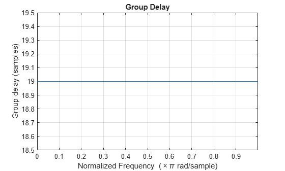
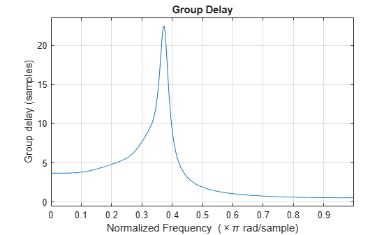
Calculate the group delay of the IIR lowpass filter. The FIR filter has a constant group delay (linear phase), while its IIR counterpart does not.

grpdelay(IIRLPF)

Figure Figure 6: Group delay contains an axes object. The axes object with title Group delay, xlabel Normalized Frequency ( times pi blank rad/sample), ylabel Group delay (in samples) contains an object of type line.

Create a lowpass filter using the dsp.LowpassFilter System object™. Setting the NormalizedFrequency property to true designs the filter with frequency specifications in normalized frequency units.

LPF = dsp.LowpassFilter(NormalizedFrequency=true)
LPF = 
  dsp.LowpassFilter with properties:

               FilterType: 'FIR'
    DesignForMinimumOrder: true
        PassbandFrequency: 0.3628
        StopbandFrequency: 0.5442
           PassbandRipple: 0.1000
      StopbandAttenuation: 80
      NormalizedFrequency: true

  Use get to show all properties

Create a spectrumAnalyzer object to visualize the input and output signal spectra. With a sample rate of 44.1e3 Hz, the passband frequency and the stopband frequency of the filter translate to 8000 Hz and 12000 Hz, respectively.

SA = spectrumAnalyzer(SampleRate=44.1e3,...
                      PlotAsTwoSidedSpectrum=false,ShowLegend=true,...
                      YLimits=[-150 30],...
                      Title='Input Signal and Output Signal of Lowpass Filter');
SA.ChannelNames = {'Input','Output'};

Run the lowpass filter algorithm to filter the white Gaussian noisy input signal. View the input and output signals using the spectrum analyzer.

for k = 1:100
    Input = randn(1024,1);
    
    Output = LPF(Input);
    
    SA([Input,Output]);
end

Set up the IIR lowpass filter. The sampling rate of the white Gaussian noise is 44,100 Hz. The passband frequency of the filter is 8 kHz, the stopband frequency is 12 kHz, the passband ripple is 0.1 dB, and the stopband attenuation is 80 dB.

Fs = 44.1e3;
filtertype = 'IIR';
Fpass = 8e3;
Fstop = 12e3;
Rp = 0.1;
Astop = 80;
LPF = dsp.LowpassFilter(SampleRate=Fs,...
                             FilterType=filtertype,...
                             PassbandFrequency=Fpass,...
                             StopbandFrequency=Fstop,...
                             PassbandRipple=Rp,...
                             StopbandAttenuation=Astop);

View the magnitude response of the lowpass filter.

fvtool(LPF)

Figure Figure 1: Magnitude Response (dB) contains an axes object. The axes object with title Magnitude Response (dB), xlabel Frequency (kHz), ylabel Magnitude (dB) contains 2 objects of type line.

Create a spectrum analyzer object.

SA = spectrumAnalyzer(SampleRate=Fs,...
    PlotAsTwoSidedSpectrum=false,...
    ShowLegend=true,YLimits=[-150 30],...
    Title='Input Signal and Output Signal of IIR Lowpass Filter');
SA.ChannelNames = {'Input','Output'};

Filter the white Gaussian noisy input signal. View the input and output signals using the spectrum analyzer.

for k = 1:100
    Input = randn(1024,1);

    Output = LPF(Input);

    SA([Input,Output]);
end

Measure the frequency response characteristics of a lowpass filter. Create a dsp.LowpassFilter System object with default properties. Measure the frequency response characteristics of the filter.

LPF = dsp.LowpassFilter
LPF = 
  dsp.LowpassFilter with properties:

               FilterType: 'FIR'
    DesignForMinimumOrder: true
        PassbandFrequency: 8000
        StopbandFrequency: 12000
           PassbandRipple: 0.1000
      StopbandAttenuation: 80
      NormalizedFrequency: false
               SampleRate: 44100

  Use get to show all properties

LPFMeas = measure(LPF)
LPFMeas = 
Sample Rate      : 44.1 kHz  
Passband Edge    : 8 kHz     
3-dB Point       : 9.1311 kHz
6-dB Point       : 9.5723 kHz
Stopband Edge    : 12 kHz    
Passband Ripple  : 0.08289 dB
Stopband Atten.  : 81.6141 dB
Transition Width : 4 kHz     
 

Algorithms

expand all

References

[1] Shpak, D.J., and A. Antoniou. "A generalized Remez method for the design of FIR digital filters." IEEE® Transactions on Circuits and Systems. Vol. 37, Issue 2, Feb. 1990, pp. 161–174.

[2] Selesnick, I.W., and C. S. Burrus. "Exchange algorithms that complement the Parks-McClellan algorithm for linear-phase FIR filter design." IEEE Transactions on Circuits and Systems. Vol. 44, Issue 2, Feb. 1997, pp. 137–143.

Extended Capabilities

Version History

Introduced in R2015a

expand all