Implement AUTOSAR‑Compliant Field‑Oriented Control for PMSM on Infineon AURIX™ TC3x Microcontrollers
This step of the example shows how to integrate the AUTOSAR Microcontroller abstraction layer (MCAL) components and complex device drivers (CDD) with Simulink to generate production‑ready code. This example uses the BIFACES tool to integrate code and build the motor control project that you created and configured in EB Tresos Studio. The build process generates executable and linkable format (ELF) and HEX files. You can deploy these files on the Infineon AURIX TC3x Microcontroller to implement an AUTOSAR-compliant field-oriented control (FOC) algorithm to run a permanent magnet synchronous motor (PMSM).
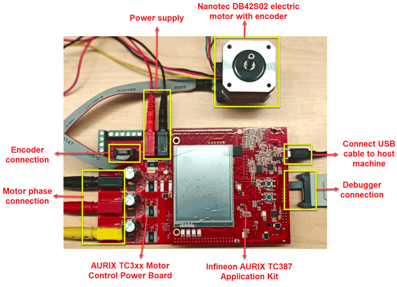
Required Hardware
Infineon AURIX TC387 Application Kit
AURIX TC3xx motor control power board
Nanotec DB42S02 electric motor
WEDL5541-B14-KIT (5 mm) incremental encoder
Hardware Connection
Connect the required hardware as shown in this figure.
Open MATLAB Project
To open a working copy of the project files for this example, in the Command Window, execute this command, and double-click AUTOSARBasedCDDMotorControlExample.prj.
openExample("infineonaurixtc3x/AUTOSARBasedCDDMotorControlExample");
This project includes these folders containing the files you need to implement the AUTOSAR-compliant motor control application.
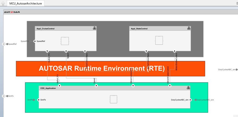
arxmlLibrary— AUTOSAR-compliant Simulink blocks generated from MCAL ARXML (ADC, DIO ), CDD ARXML (UART ) files, corresponding runnables, and API calls. The example uses these Simulink blocks. You can generate similar libraries using theprocessAllModulesfunction included in thesupportFilesfolder.bswmdDictionary— Simulink data dictionary,bswmdDictionary.sldd,that defines Simulink representations corresponding to the MCAL and CDD implementation data types described in the AUTOSAR XML (ARXML) file. This example uses these definitions during code generation of the AUTOSAR model. You can generate a different data dictionary using theimportARXML2slddscript included in thesupportFilesfolder.code— Initialization and runnable files. The runnable files implement AUTOSAR software component runnables.components— Simulink models used in the AUTOSAR architecture model in theintegModelsfolder.integModels—MCU_AutosarArchitectureandMCU_AutosarPlantSystemmodels which you can use for simulation and code generation respectively. TheMCU_AutosarArchitecturemodel consists of two main parts:MCU, which contains the Microcontroller software (MCU) andInverterAndMotor, which represents a simulated plant including the motor and inverter. Microcontroller software includes theMCU_AutosarArchitecturemodel which contains these software components:Appl_CruiseControl— This Application layer component implements the high-level motor speed control algorithm. This acts as the outer field-oriented control (FOC) loop that controls the speed of a PMSM using a proportional integral (PI) controller. This loop usually runs at a slower rate than the inner loop controlling the motor torque.Appl_StateControl— This Application layer component manages the motor’s operational states by transitioning throughIDLE,CALIB,OPEN_LOOP,POSITION_LOCK, andCLOSED_LOOP, holding each state for one second.CDD_Application— This CDD layer component implements the low-level motor torque or current control algorithm. This acts as the inner FOC loop of PMSM that controls the torque by controlling the motor currents using two separate PI controllers (for d- and q-axis currents). This loop usually runs at a faster rate than the outer loop controlling the motor speed. TheCDD_TorqueControlmodel runs at 50 μs andStateControlandCruiseControlmodels run at 500 μs. For more information about FOC, see Field-Oriented Control (Motor Control Blockset).
rte— Files that implement bare-metal scheduler which handles data exchange between the AUTOSAR components. The scheduler uses files such asRte_CDD_TorqueControl.c,Rte_CruiseControl.c,Rte_StateControl.c, and the corresponding header files. These files coordinate the execution of AUTOSAR runnables and enable communication between software components at a fixed periodic rate. You can use these runtime environment (RTE) files directly in your AUTOSAR project or generate your own in EB Tresos Studio using the rte extension. For more information, see Configure AUTOSAR Runnables and Events (AUTOSAR Blockset) and Configure AUTOSAR Runnable Execution Order (AUTOSAR Blockset).scripts— MATLAB scripts supporting the models.The
supportFiles— AUTOSAR XML files, metadata API files, and MATLAB scripts for ARXML library creation, data dictionary generation, and for copying the generated files. For more information on ARXML files, see Get Started with ARXML Files (Vehicle Network Toolbox).The
processAllModulesscript automates the creation of Simulink ARXML libraries and subsystem‑wrapped C‑Function blocks for three AUTOSAR modules:Dio,Adc, andUart.The
copyProjectFilesfunction automates extracting generated AUTOSAR code, copying required source files into the project structure, copying Simulink code to the external development platform, and assembling all supporting drivers and Simulink artifacts into your AUTOSAR project.The
importARXML2slddscript creates and updates a Simulink Data Dictionary (bswmdDictionary.sldd) with AUTOSAR architectural data.
Simulate Model in Simulink
Before you generate code and implement the motor controller application, simulate the plant system model to verify the controller performance.
1. Open the MCU_AutosarPlantSystem model.
2. To simulate the model, in the Simulink toolstrip, under Simulation tab, in the Simulate section, click Run.
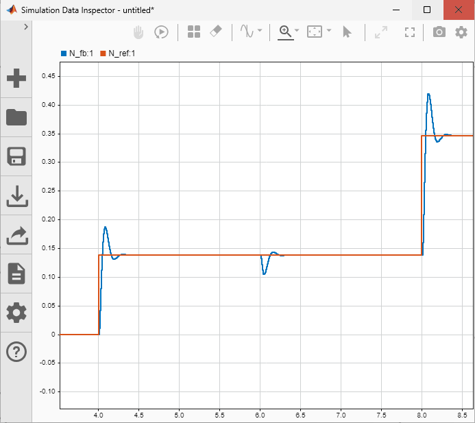
3. To view the simulation results, in the Review Results section of the toolstrip, click Data Inspector. You can observe that the speed feedback signal approximately matches with the reference speed.
Generate Code in Simulink
To export composition and component ARXML descriptions and generate component code, follow these steps:
1. Open the MCU_AutosarArchitecture model.
2. You can configure the XML options for the ARXML export, in the Simulink toolstrip, in the Modeling tab, in the Share section, click XML Options. The XML Options dialog box opens and it shows XML options for the classic architecture model. Modifications you make to these options are inherited by every component in the hierarchy. For more information, see Configure AUTOSAR XML Options (AUTOSAR Blockset).
3. To generate code and export ARXML from the architecture model, select Share > Generate Code and Export ARXML. The Export Composition dialog box opens
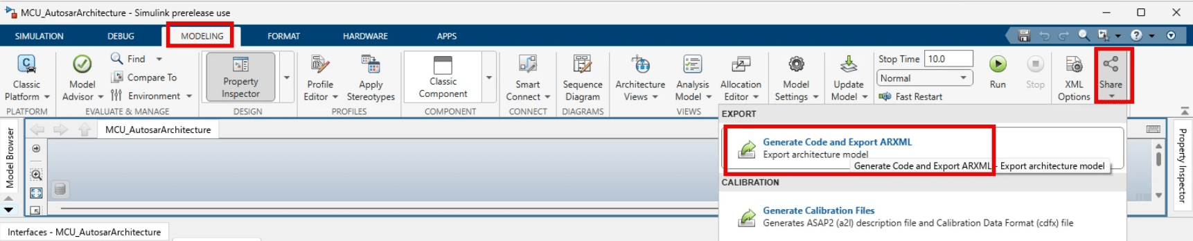
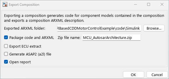
4. In the Export Composition dialog box, click Browse button and set Exported ARXML folder path to Simulink folder of the code folder included in this example. Ensure that Package code and ARXML and Open report parameters are enabled and click OK. Simulink places the generated MCU_AurosarArchitecture.zip file in the code folder.
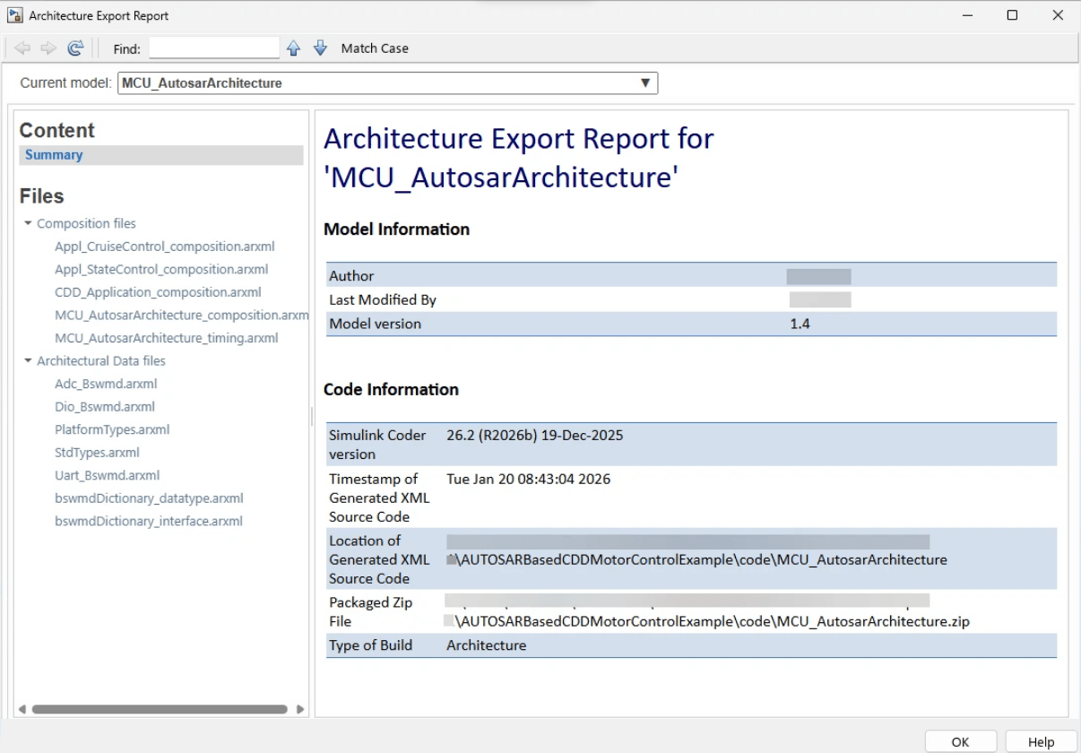
5. After exporting the ARXML files, Simulink opens Architecture Export Report where you can explore the exported ARXML files. For more information, see Export Composition and Component ARXML Descriptions from AUTOSAR Blockset Architectures (AUTOSAR Blockset).
Import Simulink Code to BIFACES
This example uses the build and integration framework for automotive controller embedded software (BIFACES) to integrate the Simulink generated AUTOSAR code and the MCAL project code to implement the motor control application. To import the composition and component ARXML descriptions and generated component code to BIFACES, you must use the copyProjectFiles function included in the supportFiles folder. This function copies, extracts, and organizes the Simulink generated AUTOSAR code, support packages, and Infineon iLLD drivers into the AUTOSAR project structure for BIFACES. It also creates corresponding folders in the BIFACES project.
1. Set srcFolder to the example directory, where Simulink placed the generated code in the Generate Code in Simulink Step.
2. Set projectPath to the directory containing the MCAL project created and configured in the Configure MCAL Modules and Generate Code in EB Tresos Studio step.
3. To import the Simulink generated AUTOSAR code to BIFACES, execute these commands in the Command Window:
srcFolder   = 'J:/AUTOSARBasedCDDMotorControlExample'; % Specify path to the example folder containing the generated Simulink code and models.
projectPath = 'J:/MotorControlDemo'; % Specify path to the MCAL project
copyProjectFiles(srcFolder, projectPath);
Integrate Simulink and MCAL codes
So far, you have imported the MCAL project and Simulink generated code, support packages, and Infineon iLLD drivers into the AUTOSAR project structure in the BIFACEs tool. Next, you must integrate the initialization files and runnables to ensure MCAL drivers, AUTOSAR Basic Software (BSW) modules, and Simulink model configurations start up correctly and consistently every time the application algorithm runs.
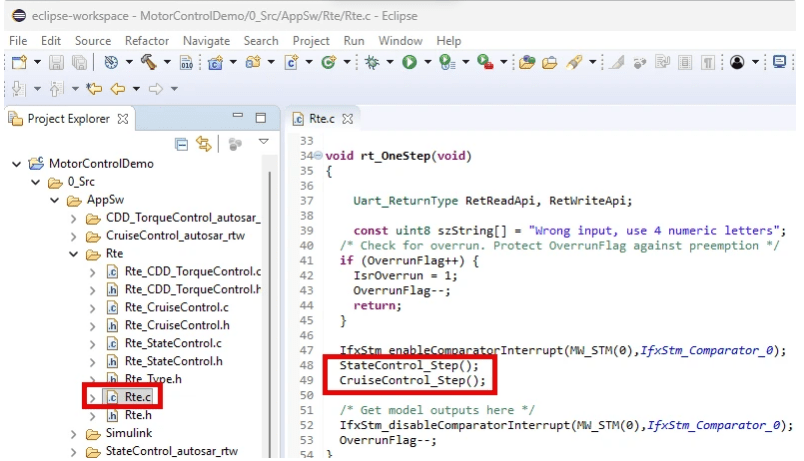
1. Run-time environment (RTE) files help in integrating the runnables. In the BIFACES project workspace, go to <Project_Path>/0_Src/AppSw and place a copy of the Rte folder included in the example project. This Rte folder contains RTE files generated using a bare-metal scheduler with a base rate of 500 μs.
2. Ensure that the scheduler information, runnables, and initialization files are included in the Rte.c file.
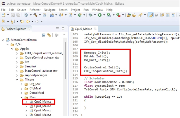
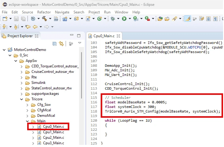
3. To customize the motor control project to use the included scheduler and integrate the necessary runnables and initialization files, you must modify Cpu0_Main.c, located at <Project_Path>/0_Src/AppSw/Tricore/Main. This example includes a reference Cpu0_Main.c file in the code/updateFiles folder.
In the BIFACES project workspace, open Cpu0_Main.c and include the below code:
To use the included scheduler and motor control application algorithms, include these header files.
#include "TriCore0_Ifx_STM.h"
#include "Rte_CDD_TorqueControl.h"
#include "Rte_CruiseControl.h"
Include the below code that defines the base rate and clock of the scheduler. It calls the
TriCor0_Aurix_STM_Configfunction from the RTE files.
float modelBaseRate = 0.0005;
float systemClock = 300;
TriCore0_Aurix_STM_Config(modelBaseRate, systemClock);
To integrate the initialization files, include the below code:
DemoApp_Init();
MW_Adc_Init();
MW_Uart_Init();
CruiseControl_Init();
CDD_TorqueControl_Init();
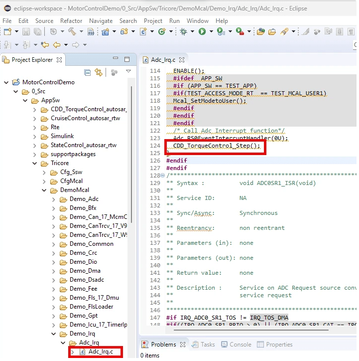
Alternatively, you can also generate the runnables in EB Tresos Studio and use them in your application project. This example includes a reference Adc_Irq.c file in the code/updateFiles folder.
4. Add the header files and the CDD runnables in the Adc_Irq.c file located at <Project_Path>/0_Src/AppSw/Tricore/DemoMcal/Demo_Irq.
In the BIFACES project workspace, open Adc_Irq.c and include the below code:
To use the included scheduler and motor control application algorithms, include these header files.
#include "Adc.h"
#include "Irq.h"
#include "IFX_Os.h"
#include "Rte_CDD_TorqueControl.h"
#include "CDD_TorqueControl.h"
To add the CDD runnable for ADC, include the below code.
CDD_TorqueControl_Step();
Note:
In this example, the ADC module is updated for a motor control application. After you import the MCAL configuration to BIFACES, the corresponding ADC group names and configurations in
Adc_Cfg.h(located at <Project_Path>/0_Src/AppSw/Tricore/CfgMcal/inc/Adc_Cfg.h) andAdc_Demo.c(located at <Project_Path>/0_Src/AppSw/Tricore/DemoMcal/Demo_Adc/Adc_Demo.c) must match. Any mismatch results in undeclared identifiers build errors. For example, the ADC software trigger group that you have deleted in the Configure MCAL Modules and Generate Code in EB Tresos Studio step might cause a build error. You can prevent the error by including the following definitions inAdc_Demo.c.
#define AdcConf_AdcGroup_AdcSWGroup 0
#define AdcConf_AdcGroup_AdcHWGroup 1
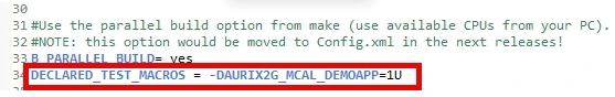
Default settings related to the MCAL demo application in the
Config.mkfile (located at <Project_Path>/1_ToolEnv/0_Build/1_Config/Config.mk) have been updated for a motor control application in this example.
Build Project and Generate Executables
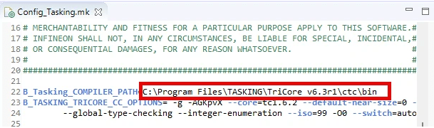
1. Verify the specified compiler path is the path where your compiler is installed. For example, verify and correct the path of the Tasking compiler installation path in Config_Tasking.mk located in <Project_Path>/1_ToolEnv/0_Build/1_Config/Config_Tricore_Tasking.
2. To build the project, in the Project tab, click Build Project.
3. Depending on the compiler used, a successful build creates ELF and HEX files in the 2_Out folder.
Deploy on TC3x Hardware Board
1. Complete the hardware connections.
2. To deploy on the hardware board, open AURIX Flasher and check connectivity. Then, select the generated ELF or HEX file to flash, and click Flash.
3. For serial logging, open any serial terminal tool such as PUtty, Tera Term, or hyper terminal available in BIFACES. Set Baud rate value to 115200 and specify COM port. To connect, click Open.
4. After successful connection, you can provide a reference speed in the console of the serial terminal tool and observe the motor responding to the provided speed value.
5. To observe and analyze the run time signals, open the OneEye tool and load the CDD_MotorControl.OneEye file included in the example. You can observe that the speed feedback signal approximately matches with the reference speed.