Orientation, Position, and Coordinate Convention
The Sensor Fusion and Tracking Toolbox™ enables you to track orientation, position, pose, and trajectory of a platform. A platform refers generally to any object you want to track its state.
Orientation
Orientation is defined by angular displacement. Orientation can be described in terms of point or frame rotation. In point rotation, the coordinate system is static and the point moves. In frame rotation, the point is static and the coordinate system moves. For a given axis and angle of rotation, point rotation and frame rotation define equivalent angular displacement but in opposite directions.
Sensor Fusion and Tracking Toolbox defaults to frame rotation.
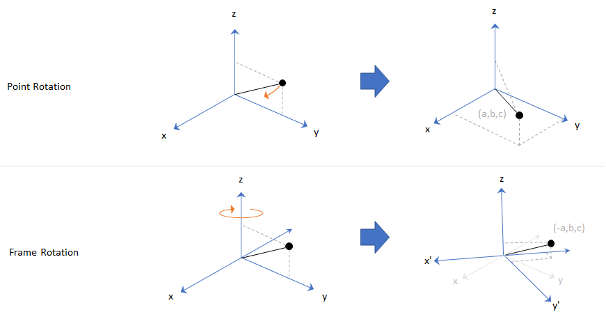
In frame representation, orientation is defined as rotation that takes the parent frame to the child frame. The choice of parent and child frames depends on the problem being solved. For example, when you manipulate the mounting of a sensor on a platform, you can select the platform body frame as the parent frame and select the sensor mounting frame as the child frame. The rotation from the platform body frame to the sensor mounting frame defines the orientation of the sensor with respect to the platform.
Local Navigation Coordinate Systems
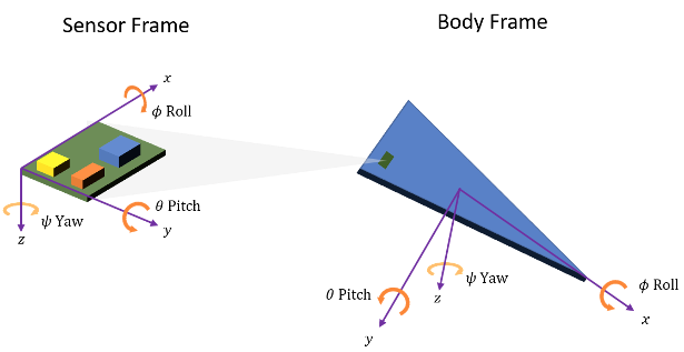
Algorithms to track orientation, position, pose, and trajectory of a platform (such as vehicle or sensor) generally require a parent reference frame against which these parameters are defined. The vehicle frame or sensor frame serves as the child frame relative to the parent reference frame. The parent frame is a type of local tangent plane coordinate system defined relative to a specific location on Earth specified by a latitude, longitude, and altitude.
The origin of the system is chosen based on the location where the measurement is made or where the vehicle, such as a robot, aircraft, or drone, is operating. Typical origins include the starting point of the trajectory, a fixed base station, or a reference point at a specific altitude. The local definition contrasts with global frames, such as ECEF (Earth-Centered-Earth-Fixed) systems, which originate at the center of the Earth.
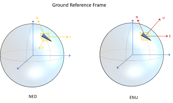
The two most common conventions for these local systems are NED (north-east-down) and ENU (east-north-up).
North-East-Down coordinate system: The north-east-down (NED) axes are oriented along the geodetic directions defined by the surface of the Earth.
The x-axis points north parallel to the geoid surface, in the polar direction.
The y-axis points east parallel to the geoid surface, along a latitude curve.
The z-axis points downward, toward the surface of the Earth, antiparallel to the outward normal of the surface.
Gravity: Because the z-axis points downward, the standard gravity vector is defined as positive g in the frame.
East-North-Up coordinate system: The east-north-up (ENU) axes are similarly oriented along geodetic directions but with a flipped vertical axis.
The x-axis points east parallel to the geoid surface, along a latitude curve.
The y-axis points north parallel to the geoid surface, in the polar direction.
The z-axis points upward, along the outward normal of the surface.
Gravity: Since the z-axis points upward, the standard gravity vector is defined as negative g in the frame.
Sensor Fusion and Tracking Toolbox primarily supports the NED (north-east-down) coordinate frame. You can
also use the ENU (east-north-up) coordinate frame in many features. In a few
functions and objects (such as geoTrajectory and gpsSensor), you need to use the ECEF (Earth-Centered-Earth-Fixed)
frame and geodetic coordinates of latitude, longitude, and altitude. For details of
ECEF and geodetic coordinates, see Coordinate Frames in Geo Trajectory.
Frame Rotation
To relate one orientation to another you must rotate a frame. The table summarizes
the z-y-x rotation conventions. You can also use other conventions, such as the
z-x-z rotation convention. See the rotation sequence (RS)
argument of quaternion for more details on these conventions.
| Variable | Euler Angle | Symbol | Output Interval (Degrees) |
|---|---|---|---|
| z | Yaw | ψ | −180 ≤ ψ < 180 |
| y | Pitch | θ | −90 ≤ θ ≤ 90 |
| x | Roll | ϕ | −180 ≤ ϕ < 180 |
A positive rotation angle corresponds to a clockwise rotation about an axis when viewing from the origin along the positive direction of the axis. The right-hand convention is equivalent, where positive rotation is indicated by the direction in which the fingers on your right hand curl when your thumb is pointing in the direction of the axis of rotation.
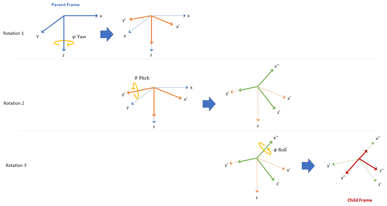
To define three-dimensional frame rotation, you must rotate sequentially about the axes. Sensor Fusion and Tracking Toolbox uses intrinsic (carried frame) rotation, in which, after each rotation, the axis is updated before the next rotation. For example, to rotate an axis using the z-y-x convention:
Rotate the parent frame about the z-axis to yield a new set of axes, (x',y',z), where the x- and y-axes have changed to x'- and y'-axes and the z-axis remains unchanged.
Rotate the new set of axes about the y'-axis, yielding another new set of axes, (x'',y',z').
Rotate this new set of axes about the x''-axis, arriving at the desired child frame, (x'',y'',z'').
This sequence of rotations follows the convention outlined in [1]. The rotation matrix required to convert a vector in the parent frame to a vector in the child frame for a given yaw, pitch, and roll is computed as:
For features that support frame-based processing, Sensor Fusion and Tracking Toolbox provides coordinates as an N-by-3 matrix, where N is the number of samples in time and the three columns correspond to the x-, y-, and z-axes. The following calculation rotates a parent frame to a child frame:
where aparent represents a N-by-3 matrix of coordinates expressed in the parent coordinate frame and achild is the resulting N-by-3 matrix of coordinates expressed in the child frame.
Sensor Fusion and Tracking Toolbox enables efficient orientation computation using the quaternion data type. To create a rotation matrix using quaternions,
use the rotmat function.
Express Gravitational Vector in Body Frame
In an NED frame, the gravitational vector can be expressed as
gNED = [0 0 9.8]; % m/s^2Consider a body frame obtained by a consecutive rotation of 20 degrees in yaw, 5 degrees in pitch, and 10 degrees in roll from the parent NED frame.
yaw = 20; % degree
pitch = 5; % degree
roll = 10; % degree
To obtain the expression of the gravitational vector in the body frame, you first obtain the quaternion corresponding to the three consecutive Euler angles.
q = quaternion([yaw pitch roll],"eulerd","zyx","frame");
Then, using the rotateframe object function, you can obtain the coordinates of the gravitational vector in the body frame as
gBody = rotateframe(q,gNED)
gBody = 1×3

   -0.8541    1.6953    9.6144
Alternately, you can obtain the coordinates using rotation matrix. First, you use the rotmat object function of quaternion to obtain the corresponding rotation matrix that transforms coordinates from the NED frame to the body frame.
R = rotmat(q,"frame");Then, obtain the coordinates of the gravitational vector in the body frame as
gBody2 = (R*gNED')'
gBody2 = 1×3

   -0.8541    1.6953    9.6144
Position
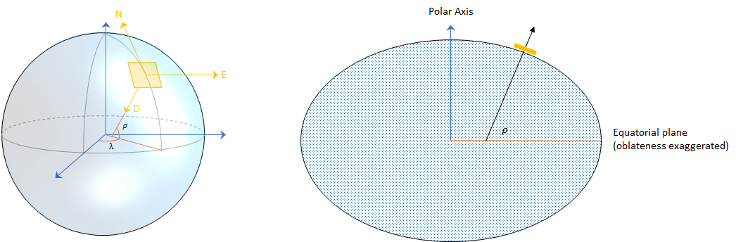
Position is defined as the translational distance from a parent frame origin to a child frame origin. For example, take the local NED coordinate system as the parent frame. In the NED coordinate system:
The origin is arbitrarily fixed to a point on the surface of the Earth. This makes the NED coordinate system local.
The x-axis points toward the ellipsoid north.
The y-axis points toward the ellipsoid east.
The z-axis points downward along the ellipsoid normal (geodetic latitude, ρ).
Azimuth and Elevation
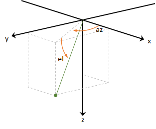
Given a vector in R3:
Azimuth is defined as the angle from the x-axis to the orthogonal projection of the vector onto the xy-plane. The angle is positive going from the x-axis toward the y-axis. Azimuth is given in degrees in the range [−180, 180).
Elevation is defined as the angle from the projection onto the xy-plane to the vector. The angle is positive going from the xy-plane to the z-axis. Elevation is given in degrees in the range [−90, 90].
Pose and Trajectory
To specify an object in 3-D space fully, you can combine position and orientation.
Pose is defined as the combination of position and
orientation. Trajectory defines how pose changes over time.
To generate ground-truth trajectories in Sensor Fusion and Tracking Toolbox, use kinematicTrajectory or waypointTrajectory. To generate Earth-centered trajectory, use geoTrajectory. To
simulate the motion of multiple platforms, use trackingScenario.
See Also
quaternion | transformMotion | Rotations, Orientation, and Quaternions
References
[1] IEEE. Standard for Distributed Interactive Simulation – Application Protocols. IEEE P1278.1/D16, Rev 18, May 2012.