Verify the Generated Code from Native Floating-Point
HDL Coder™ native floating-point technology can generate target-independent HDL code from your floating-point design. You can synthesize your floating-point design on any generic FPGA or ASIC. Floating-point designs have better precision, higher dynamic range, and a shorter development cycle than fixed-point designs. If your design has complex math and trigonometric operations, use native floating-point technology.
When representing infinitely real numbers with a finite number of bits, there can be
rounding errors with the correct rounding range of values
that the IEEE-754 standard specifies. To measure the rounding errors, you can specify the
floating-point tolerance check based on relative error or
ulp
                error
. For more information about these rounding errors, see
Relative Accuracy and ULP Considerations.
Specify the Tolerance Strategy
Before generating the testbench, specify the floating-point tolerance check for verifying the generated code.
To specify the tolerance check in the Configuration Parameters dialog box:
In the Apps tab, select HDL Coder. The HDL Code tab appears.
Click Settings. In the HDL Code Generation > Testbench pane, for Floating point tolerance check based on, specify
relative errororulp error.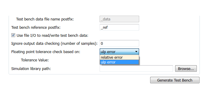
Enter the Tolerance Value and click Apply. If you choose
relative
                error
, the default is a tolerance value of1e-07. If you chooseulp error, the default tolerance value is zero. To learn more, see Numeric Considerations for Native Floating-Point.
To specify the tolerance strategy at the command-line, use:
Specify the floating point tolerance check setting by using
FPToleranceStrategy.% check for floating-point tolerance based on relative error hdlset_param('sfir_single', 'FPToleranceStrategy', 'Relative'); % check for floating-point tolerance based on the ULP error hdlset_param('sfir_single', 'FPToleranceStrategy', 'ULP');
Based on the
FPToleranceStrategysetting, enter the tolerance value by usingFPToleranceValue.% if using relative error, enter custom tolerance value hdlset_param('FP_test_16a', 'FPToleranceValue', 1e-06); % if using ULP error, enter tolerance value greater % than or equal to 1 hdlset_param('FP_test_16a', 'FPToleranceValue', 1);
Verify the Generated Code with HDL Test Bench
To generate an HDL test bench for verifying the generated code:
In the Configuration Parameters dialog box, on the HDL Code Generation > Test Bench pane, in the Test Bench Generation Output section, select HDL test bench.
In the Configuration section, make sure that Use file I/O to read/write test bench data is enabled. To generate a test bench that uses constants instead of file I/O, clear Use file I/O to read/write test bench data.
Click Apply, and then click Generate Test Bench.
To learn more about how HDL test bench generation works, see Test Bench Generation.
Verify the Generated Code with Cosimulation
To generate a cosimulation model for verifying the generated code:
In the Configuration Parameters dialog box, on the HDL Code Generation > Test Bench pane, for Cosimulation model for use with, select the cosimulation tool.
Click Apply, and then click Generate Test Bench.
After test bench generation, save the cosimulation model. In the model, double-click the
Comparesubsystem.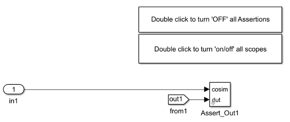
If you double-click the
Assert_Out1block, the block parameters show the Tolerance Value that you specify.To look inside the
Assert_Out1block, click the mask. If you specify the floating-point tolerance check based onulp error, the model shows aULPCheckerblock.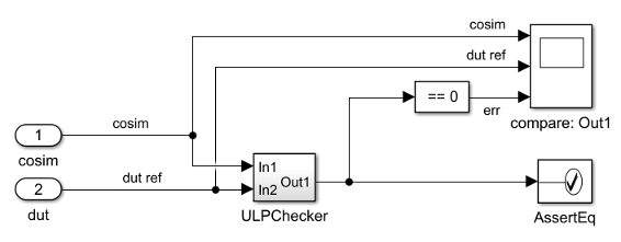
The
ULPCheckerhas a MATLAB Function block that shows how HDL Coder accounts for the ULP error when checking for numerical accuracy.If you specify the floating-point tolerance check based on
relative error, the model shows aRelErrCheckblock.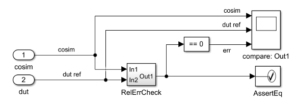
RelerrCheckhas a MATLAB Function block that shows how HDL Coder accounts for the relative error when checking for numerical accuracy.In the Simulink® Editor for the model, start simulation. At the end of cosimulation, check the
compare: Out1scope.The scope compares the difference between the result signal from the cosimulation block and the reference signal from the DUT.
See also Generate Cosimulation Model.
Limitation
When verifying the generated code, constructs that use IEEE® standards prior to VHDL-2008 are not supported with native floating-point.