addboundary
Add polyshape boundary
Syntax
Description
polyout = addboundary(
adds M boundaries, where the vectors of
x-coordinates for each boundary are listed together in a cell
array. The corresponding vectors of y-coordinates also are listed
together in a cell array. Each xi must
have the same length as the corresponding
yi, but the number of vertices can
vary among the boundaries.polyin,{x1,x2,...,xM},{y1,y2,...,yM})
polyout = addboundary(___,
specifies additional parameters for adding boundaries to a
Name,Value)polyshape for any of the previous syntaxes.
Examples
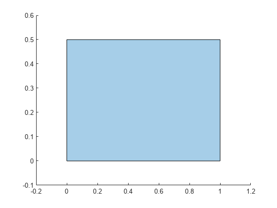
Create a rectangle, and then create a second polygon made up of the rectangle plus a triangle.
polyin = polyshape([0 0 1 1],[0 0.5 0.5 0])
polyin =
  polyshape with properties:

      Vertices: [4×2 double]
    NumRegions: 1
      NumHoles: 0
plot(polyin)
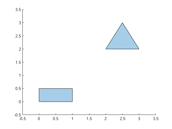
polyout = addboundary(polyin,[2 3 2.5],[2 2 3])
polyout =
  polyshape with properties:

      Vertices: [8×2 double]
    NumRegions: 2
      NumHoles: 0
plot(polyout)
Create two polyshape objects representing two triangles that do not share any points.
polyin1 = polyshape([0 1 0.5],[0 0 1]);
polyin2 = translate(polyin1,[2 0]);
plot([polyin1 polyin2])
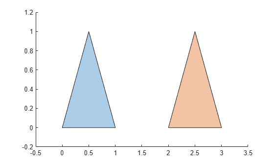
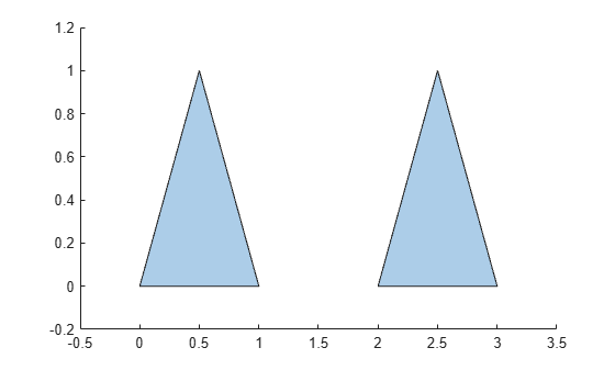
You can use the addboundary function to combine the triangles by adding the vertices of one triangle to another triangle.
polyout = addboundary(polyin1,polyin2.Vertices);
plot(polyout)
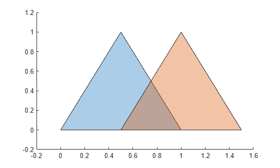
The recommended approach to combine polyshape objects is to use the union, intersect, subtract, and xor functions. While for completely separate polygons the result of using addboundary is the same as union, for intersecting or nesting polygons the results might differ. For example, create the second triangle by shifting the first triangle by 0.5 along the x-axis.
polyin2 = translate(polyin1,[0.5 0]);
plot([polyin1 polyin2])
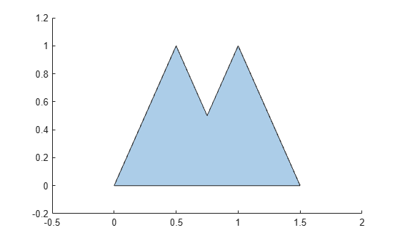
Combine the triangles by adding the vertices of one triangle to another triangle. By default, addboundary alters the resulting polyshape object vertices to produce a well-defined polyshape object when the input vertices produce intersections or improper nesting.
polyout = addboundary(polyin1,polyin2.Vertices);
Warning: Polyshape has nearly duplicate vertices, intersections, or other inconsistencies that may produce inaccurate or unexpected results. The resulting polyshape has been simplified.
plot(polyout)
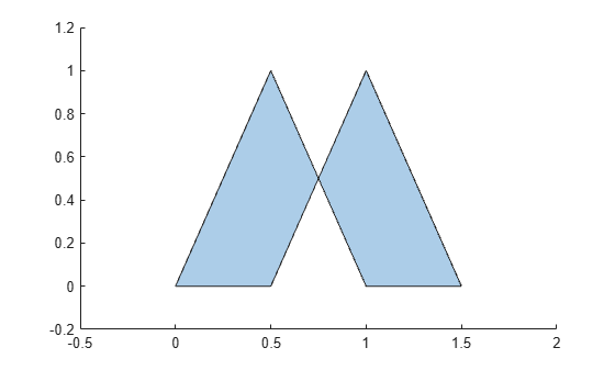
Avoid altering the resulting polyshape object vertices by setting the Simplify argument value to false. The resulting polyshape object has boundaries inside the shape.
polyout = addboundary(polyin1,polyin2.Vertices, ...
                      Simplify=false);
plot(polyout)
Combine the two triangles into a well-define polyshape object without extra boundaries by using union.
polyout = union(polyin1,polyin2);
plot(polyout)
Input Arguments
Name-Value Arguments
Extended Capabilities
Version History
Introduced in R2017b
See Also
polyshape | boundary | rmboundary | polybuffer | intersect | subtract | union | xor