Phase Noise in Oscillators
The phase noise profile of an oscillator provides insight to its stability in the frequency domain. The phase noise data you obtain from an oscillator data sheet can be flawed by the measurement limitations. To design a physically realistic model, you need to obtain reliable phase noise data from the data sheet.
Phase Noise Overview
There are two types of oscillator phase noise:
Thermal (Johnson) noise in resistors and FET channels.
Shot noise in diodes and bipolar transistors.
The sources of these two noise types have a spectral density that is constant with frequency. Therefore, they are generically referred to as additive white Gaussian noise (AWGN).
The oscillator circuit acts as a noise integrator, introducing a factor of 1/f2 to the phase noise as a function of frequency offset. In both ring oscillators and tank-tuned oscillators, this transforms the white noise in the circuit to a 1/f2 phase noise distribution.
At very low frequencies, variations in the surface conductivity due to contact and surface irregularities cause an increase in noise that varies approximately as 1/f. This noise is known as the flicker noise or 1/f noise. In ring oscillators, flicker noise adds a 1/f2 term to the phase noise distribution at low frequencies.
Oscillator Circuit
A basic oscillator circuit contains a feedback loop consisting of a feedback delay element and an amplifier. The gain of the amplifier is high enough that the feedback loop has more than unity gain at the desired frequency of oscillation. A noise source representing the amplifier noise is typically added at the output of the amplifier.

At the frequency of oscillation, the feedback loop has a small signal gain of greater than 1 and an insertion phase of 0. At that frequency, the feedback loop integrates the signal from the output of the amplifier, including the noise. The amplitude of the integral increases rapidly with time until the output of the amplifier reaches saturation. The saturated signal is used as the output of the oscillator.
The noise injected into the oscillator feedback loop generates phase noise. For more information about noise sources, see Define Device Noise Using Linear Circuit Wizard. The phase noise and the saturated output signal are simply two aspects of the same behavior.

In the time domain, the saturated output amplitude and the output load impedance define the output power. In the frequency domain, a spectral density distribution (W/Hz) describes the same output power. This is because the integral of the spectral density in the frequency domain must equal the output power as evaluated in the time domain. The tail of the spectral density distribution is known as the as 1/f2 phase noise. It can transition to 1/f3 phase noise at smaller frequency offsets. Neither 1/f2 nor 1/f3 phase noise spectral density can be integrated all the way to a frequency offset of 0. Such an integral must go to infinity requiring infinite energy. There must be a saturation point in the frequency domain as well as in the time domain.
The spectral density saturation frequency offset fsat depends on the coefficients for the 1/f2 and 1/f3 phase noise. The saturated spectral density times twice the saturation frequency offset must be nearly equal to the output power level. Since the spectral density function must be a single continuous function, high phase noise coefficients result in a larger saturation frequency offset and therefore a lower saturation level. In essence, the oscillator output frequency varies between ±fsat.
There are two fundamental types of oscillator circuits: the ring oscillator and the resonator-tuned or tank-tuned oscillator. The response of the feedback path for a ring oscillator extends to DC. Therefore, a 1/f2 factor is applied to the flicker noise, resulting in a 1/f3 phase noise component at low frequency offsets. This 1/f3 component is added to the 1/f2 white Gaussian noise component at higher frequency offsets. The feedback path of a tank-tuned oscillator has a bandpass response. So, the phase noise of the tank-tuned oscillator does not include this 1/f3 component.
Ring Oscillator
In this five-section ring oscillator circuit, the capacitive loading on the inverter outputs introduces delay into the feedback loop and the inverters provide the gain, nonlinear saturation, and output noise.

You can form a ring oscillator using an odd number of sections. Ring oscillators have the advantage of occupying a relatively small area in an integrated circuit. But the loop gain in a ring oscillator goes to DC, which makes them susceptible to flicker noise as well as Johnson noise, resulting in higher phase noise at low frequency offsets.
Resonator-Tuned Oscillator
In a resonator-tuned oscillator circuit, the feedback element is a single-section bandpass filter formed by a resonant structure such as an LC tank circuit, a microwave cavity, or piezoelectric crystal.

The gain, nonlinear saturation, and output noise are usually supplied by a transistor circuit. Resonator-tuned oscillators typically have much lower phase noise than ring oscillators and are typically much more stable with temperature. But the resonator-tuned oscillator requires a much larger area in the IC than a ring oscillator due to the presence of the inductor.
Relationship Between Jitter and Phase Noise
Jitter is a time-domain phenomenon characterized by the variation of the oscillator output cycle period between one output cycle and the next. There is a finite slew rate for either a rising or a falling output edge. That slew rate converts either voltage or current noise with respect to a fixed threshold crossing value into displacements in the time domain. This variation in the cycle period is referred to as period jitter. It is inherently a discrete sampled process where sample time equals the average output period.
Phase noise is the variation of the output phase with respect to the ideal output phase, and is a continuous process in both the time and frequency domains. That is, the output phase is defined for all points in time, and through the Fourier transform all points in the frequency domain.
Although jitter and phase noise are fundamentally different concepts, a rigorous derivation of the mathematical relationship between the two concepts exists in [1]. This method used in [1] applies a sample and hold (windowing) process to the discrete time-domain period jitter samples and then transforms them to the frequency domain. Integrals in the frequency domain then provide a direct mathematical relationship between jitter and phase noise.
For white Gaussian device noise such as Johnson noise, the jitter is a white noise process with variance στ2. For phase noise for output frequency f0 and frequency offset f, the spectral density of the phase noise is:
Though essentially the same mathematics, the phase noise due to flicker noise ends up being proportional to 1/f3. So, the phase noise from a ring oscillator is the sum of a 1/f2 component and a 1/f3 component. [1, 2, 3]
Since resonator-tuned oscillators have bandpass filter feedback paths, they do not provide a conduction path at the low frequencies associated with flicker noise. Therefore it is only the white noise in the passband of the feedback path that contributes to phase noise, and the close-in phase noise exhibits a 1/f2 characteristic.
Measurement Limitations
Phase noise is typically measured using a spectrum analyzer. There are some limitations to the measurement that require workarounds.
Resolution Bandwidth
For each frequency point, the spectrum analyzer reports all the energy detected in the resolution bandwidth surrounding that frequency point. But no resolution filter has perfect out-of-band rejection. So there can be a signal in the rejection band that is powerful enough to overcome the finite rejection of the filter and distort the energy reported at the frequency point. This distortion is particularly common when measuring oscillator phase noise at low frequency offsets.
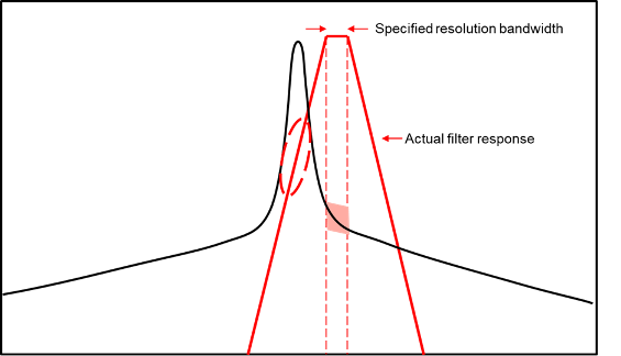
In this diagram, the desired measurement is highlighted in pink. But the actual response of the resolution filter allows significant energy from the primary output of the oscillator to leak into the reported result, as shown by the dashed red oval. This out of band leakage can easily have far more energy than the desired signal.
You can counteract this problem by reducing the resolution bandwidth to the point where the out-of-band leakage is no longer a problem at the desired offset frequency. But this increases the run time of the measurement. The oscillator output frequency must also be relatively constant over that long period
Noise Floor
Even though spectrum analyzers typically have a very large dynamic range, they all have a noise floor. At large enough frequency offsets, the phase noise from the oscillator usually goes below that noise floor. So the data can represent the noise floor of the instrument and not the phase noise of the device under test.

Since phase noise and noise floor measurements are stochastic processes (random signals), there is no easy way to avoid this limitation. The best you can do is to amplify the signal to be measured without exceeding the upper limit on the input power to the instrument.
Frequency Drift
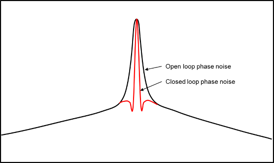
Sometimes the output frequency of the oscillator under test can drift too far during measurement. In some cases, your design can allow the oscillator under test to be phase locked to a more stable reference, thus making the measurement possible. However, when taking this approach, you must set the PLL bandwidth to a small value so that the PLL response does not distort the measured phase noise at the smallest frequency offset to be measured.
Obtaining Accurate Data from Data Sheet
There are data sheets that match the expected behavior of oscillators quite accurately over many decades of frequency offset. But it is also common for data sheets to offer data flawed by the measurement limitations. Extracting realistic data from these data sheets can require some effort. This table shows some common distortions and their probable cause.
| Distortion | Probable Cause | Graphical Representation |
|---|---|---|
| The phase noise at low frequency offsets looks too high. | The resolution bandwidth used in the measurement could have been too high. |
|
| The phase noise flattens at higher frequency offsets. | Phase noise is below the measurement noise floor. |
|
| The phase noise at low frequency offsets looks too low. | The oscillator could be operating inside a PLL at the time of measurement. |
|


You can use the Ring Oscillator VCO block to estimate a realistic phase noise profile for an oscillator.
Double-click the Ring Oscillator VCO block to open the Block Parameters dialog box.
In the Impairment tab, enter the phase noise (Phase noise level (dBc/Hz) parameter) and the frequency offset (Phase noise frequency offset (Hz) parameter) from the data sheet.
Click the Estimate phase noise parameters button to calculate the Period jitter (S) and Flicker corner frequency (Hz) parameters.
Click the Plot fit button to plot the resulting fit for the specified data.
Adjust the period jitter, flicker corner frequency or both and plot the results again to obtain a more realistic fit for your design.
Signal Spectral Density vs. Phase Noise Spectrum
Phase noise is typically measured by a spectrum analyzer. But there is a fundamental difference between the signal spectral density measured by a spectrum analyzer and the phase noise spectrum of the oscillator output signal.
Power and energy are fundamental to the definition of the spectral density of a signal. But phase is an abstract variable that is not directly associated with energy. In that sense, the phase noise measured by a spectrum analyzer depends on the approximation that the phase noise is a linear function of the spectral density of the signal. This approximation is valid when the phase noise is a small fraction of a single cycle of the signal. But for very large phase noise spectral densities that can exist very close to the frequency of oscillation, this approximation becomes invalid.
Period jitter is the variation in the period of the oscillator output signal. You can mathematically measure the period jitter directly, for instance in a time-domain simulation. You can then calculate the phase noise directly from the measured period jitter. When phase noise is determined in this way, there is no fundamental constraint on the spectral density of the phase noise.
References
[1] Abidi, A.A. “Phase Noise and Jitter in CMOS Ring Oscillators.” IEEE Journal of Solid-State Circuits 41, no. 8 (August 2006): 1803–16.
[2] Hajimiri, A., and T.H. Lee. “A General Theory of Phase Noise in Electrical Oscillators.” IEEE Journal of Solid-State Circuits 33, no. 2 (February 1998): 179–94.
[3] Hajimiri, A., S. Limotyrakis, and T.H. Lee. “Jitter and Phase Noise in Ring Oscillators.” IEEE Journal of Solid-State Circuits 34, no. 6 (June 1999): 790–804.