Main Content

Network Coupler (Voltage-Voltage)

Split network at an electrical connection

Since R2022a

  • Network Coupler (Voltage-Voltage) block

Libraries:
Simscape / Utilities / Network Couplers

Description

The Network Coupler (Voltage-Voltage) block provides a starting point for you to split a Simscape™ network into two coupled networks at an electrical connection. Use this block for splitting power networks where connection cables are modeled as resistors and inductors connected in series, and where parts of the network do not have a local electrical reference connection. The inductances in this type of scenario do not allow the use of current sources at the interface, and therefore this block presents a voltage source to both networks.

You cannot simply drive the voltage source for Network 2 based on a voltage measurement for Network 1 (and the other way around) because then the definition is cyclic and contains no constraint on the currents flowing into the two networks, which must sum to zero. To introduce the constraint on currents, the two voltage sources have an added internal source resistance.

The discrete-time equations defining the values of the two voltage sources are:

Vs1(n+1)=V2(n)+i2(n)R1Vs2(n+1)=V1(n)+i1(n)R2

where:

  • Vs1, Vs2 — Voltages of the two internal sources.

  • R1, R2 — Resistances of the two internal sources.

  • i1, i2 — Currents flowing from the connected networks into the sources.

  • V1, V2 — Voltages presented to the connected networks.

  • n — Sample number.

When there is no load connected to either side, then the poles are at +-1, that is, on the unit circle. The connected network can act to either stabilize the poles (they end up inside the unit circle), or destabilize (they end up outside of the unit circle).

Generally, it is best when the series inductances and resistances of the two coupled networks are approximately equal because this results in the slowest set of closed-loop poles.

Both of the port interfaces of the Network Coupler (Voltage-Voltage) block are implemented as voltage sources. Therefore, you cannot connect this block to a voltage loop, such as a set of series-connected voltage sources and capacitors, because this would cause an Index-2 topology (for more information, see Avoiding Numerical Simulation Issues).

To facilitate working with models that contain arrays of electrical nodes or three-phase connection, the Port 1 Interface and Port 2 Interface subsystems contain custom blocks, such as Controlled Voltage Source or Current Sensor. These custom blocks are based on the equivalent Foundation library blocks but are modified to support vectorized and three-phase electrical nodes. The source files for these custom blocks are located in the following namespace:

matlabroot/toolbox/physmod/simscape/library/m/+foundation/+internal/+couplers/+electrical

where matlabroot is the MATLAB® root directory on your machine, as returned by entering

matlabroot

at the MATLAB command prompt. The namespace contains source files for voltage and current sources and sensors, as well as a resistor and an electrical reference with array and three-phase support. You can use these blocks to customize your network coupler configuration.

Working with the Block on the Model Canvas

When you add the block to your model and double-click it, the Network Coupler (Voltage-Voltage) subsystem opens.

Network Coupler (Voltage-Voltage) subsystem diagram

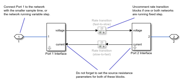
The Port 1 Interface block contains the dynamics that break the algebraic loop. Double-click this block to set most of the Network Coupler (Voltage-Voltage) subsystem parameters and view the derived values.

However, unlike most of the other coupler blocks, the Port 2 Interface block also has one parameter, Port 2 voltage source resistance (ohms), which you need to set separately.

The rate transition blocks are, by default, commented through. Uncomment them if at least one of the coupled networks is running fixed step.

Using the Derived Values to Estimate Block Parameters

The Analysis tab asks you for information about the series-connected resistance and inductance of the two coupled networks and provides advice on values of R1 and R2, to ensure stability. If at least one of your coupled networks has switching, then use the smallest series resistance value and the largest series inductance value.

For most applications, following the recommended values results in a stable simulation, but on occasion you may need to experiment with values for R1 and R2.

The Update button lets you recalculate the derived values after you change the parameters of the connected networks.

Ports

Conserving

expand all

If one of the coupled networks is running variable step, connect it to port 1 of the Network Coupler (Voltage-Voltage) block. If both networks are running fixed step, connect this port to the network with the smaller sample time. If both networks are running variable step, or fixed step with the same step size, then the block polarity does not matter.

If one of the coupled networks is running variable step, connect port 2 of the Network Coupler (Voltage-Voltage) block to the fixed-step network. If both networks are running fixed step, connect this port to the network with the larger sample time.

Parameters

expand all

Main

Select this check box when breaking connections between three-phase electrical ports. Because the top-level subsystem is unmasked, you need to select this check box both for Port 1 Interface and Port 2 Interface blocks. Selecting this check box disables the Electrical node array size parameter because ports 1 and 2 become three-phase electrical ports.

Specify the size of the electrical node array connected to the two electrical ports, 1 and 2. Because the top-level subsystem is unmasked, you need to set this parameter to the same value both for Port 1 Interface and Port 2 Interface blocks.

If you are breaking a regular electrical connection, leave the default value of 1 unchanged.

Dependencies

To enable this parameter, clear the Use three-phase electrical connections check box.

Specify the resistance value for the internal voltage source connected to Network 1.

Specify the resistance value for the internal voltage source connected to Network 2. Because the top-level subsystem is unmasked, you need to set this parameter to the same value both for Port 1 Interface and Port 2 Interface blocks.

Select how the coupled networks are sampled:

  • Variable step at ports 1 and 2 — Both networks are variable-step.

  • Variable step at port 1 and fixed step at port 2 — Network 1 is variable-step and Network 2 is fixed-step.

  • Fixed step both ports with common sample time — Both networks are fixed-step, with the same step size.

  • Fixed step both ports with faster sampling at port 1 — Both networks are fixed-step, with different step sizes.

Specify sample time for Network 1, in seconds.

Dependencies

To enable this parameter, set the Sampling type parameter to Fixed step both ports with common sample time or Fixed step both ports with faster sampling at port 1.

Specify sample time for Network 2, in seconds.

Dependencies

To enable this parameter, set the Sampling type parameter to Variable step at port 1 and fixed step at port 2 or Fixed step both ports with faster sampling at port 1.

Select this check box to enable the prediction (discrete->continuous) algorithm. For more information, see Prediction and Smoothing.

Dependencies

To display this option, set the Sampling type parameter to Variable step at port 1 and fixed step at port 2.

Select this check box to enable the smoothing (continuous->discrete) algorithm. For more information, see Prediction and Smoothing.

Dependencies

To display this option, set the Sampling type parameter to Variable step at port 1 and fixed step at port 2.

Specify time constant, in seconds, for the first-order filter that the smoothing algorithm uses to remove unwanted high-frequency information.

Dependencies

To enable this parameter, select the Use smoothing when connecting variable step to fixed step check box.

Select this check box to enable the prediction (slow->fast) algorithm. For more information, see Prediction and Smoothing.

Dependencies

To display this option, set the Sampling type parameter to Fixed step both ports with faster sampling at port 1.

Select this check box to enable the smoothing (fast->slow) algorithm. For more information, see Prediction and Smoothing.

Dependencies

To display this option, set the Sampling type parameter to Fixed step both ports with faster sampling at port 1.

The smoothing algorithm works by averaging the last N samples. You specify N by using this parameter.

Dependencies

To enable this parameter, select the Use smoothing when connecting fast to slow sample times check box.

Analysis

Specify approximate series resistance at port 1, in ohms.

Specify approximate series inductance at port 1, in H.

Specify approximate series resistance at port 2, in ohms.

Specify approximate series inductance at port 2, in H.

For information on how to use the Derived values section, see Using the Derived Values to Estimate Block Parameters.

Initial Conditions

Specify initial condition for the voltage at port 1, in V.

Specify initial condition for the current flowing into port 1, in A.

Extended Capabilities

C/C++ Code Generation
Generate C and C++ code using Simulink® Coder™.

Version History

Introduced in R2022a

expand all