For Each
Control block for for-each subsystem
Description
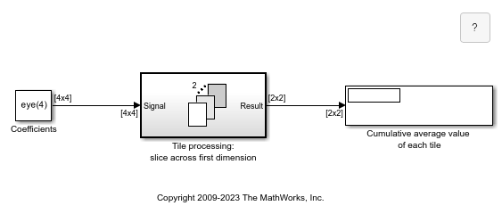
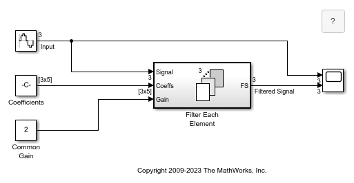
The For Each block serves as a control block for the For Each Subsystem block. Specifically, the For Each block enables the blocks inside the for-each subsystem to process the elements of either input signals or mask parameters independently. Each block inside this subsystem that has states maintains a separate set of states for each element or subarray that it processes. As the set of blocks in the subsystem processes the elements or subarrays, the subsystem concatenates the results to form output signals.

Use a for-each subsystem to iteratively compute outputs after changing inputs or mask parameters. To do so, configure the partitioning of input signals or mask parameters in the For Each block dialog box.
Partition Input Signals to the Subsystem
To specify which input signals to partition for each iteration in a for-each subsystem, use the Input Partition tab in the dialog box of the For Each block. When specifying a signal to be partitioned, specify the Partition Dimension, Partition Width, and Partition Offset parameters.
Partition Mask Parameters of the Subsystem
You can partition the mask parameters of a For Each Subsystem block. Partitioning is useful for systems that have identical structures in each iteration but different parameter values. In this case, changing the model to partition extra input signals for each parameter is cumbersome. Instead, add a mask parameter to a for-each subsystem. For more information, see Create a Simple Mask. To select the mask parameter for partitioning, use the Parameter Partition tab of the For Each block dialog box. For more information, see Select Partition Parameters, below.
Concatenate Output
Define the dimension along which to concatenate the results by specifying the Concatenation Dimension in the Output Concatenation tab.
The results generated by the block for each subarray are stacked along the concatenation dimension. By default, dimension 1 (y-axis) is used, meaning that the results are stacked vertically. However, if you specify a concatenation dimension of 2, the results concatenate along the horizontal direction (x-axis). Thus, if the process generates row vectors, then the concatenated result is a matrix in the first case and a row vector in the second case.
Select Partition Parameters
When selecting an input signal or subsystem mask parameter for partitioning, you need to specify how to decompose it into elements or subarrays for each iteration. Do this by setting integer values for the Partition Dimension, Partition Width, and Partition Offset parameters.
As an illustration, consider an input signal matrix A of the
form:

The labels d1 and
d2, respectively, define dimensions 1
and 2. If you retain the default setting of 1 for both the
partition dimension and the partition width, and 0 for the
partition offset, then Simulink® slices perpendicular to partition dimension 1 at a width equal to the
partition width, that is one element:

Matrix A decomposes into these three row vectors:

If instead you specify 2 as the partition dimension,
Simulink slices perpendicular to dimension 2 to form three column
vectors:

In addition to setting the Partition Dimension to
2, if you set the Partition Width to
2 and the Partition Offset to
-1, Simulink uses two overlapping 3-by-2 partitions for processing.

By default, all partitions of the input signal or mask parameter are processed. To
process a subset of the partitions, enter the number of partitions to process as the
Number of iterations. In the matrix examples above, if
Partition Offset is set to 0 (the
default) and Number of iterations is set to
2, only the first 2 rows or columns of the input matrix
A are processed.
Note
Only signals are considered one-dimensional in Simulink. Mask parameters are row or column vectors, according to their orientation. To partition a row vector, specify the partition dimension as 2 (along the columns). To partition a column vector, specify the partition dimension as 1 (along the rows).


