Signal Properties
View and edit signal properties
Description
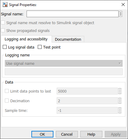
Use the Signal Properties dialog box to view and edit properties for signals in your model. Using the Signal Properties dialog box, you can mark a signal for logging, specify a signal name, and configure logging options, including which data points to log and the logging sample time.
When your model is configured for concurrent execution, the Signal Properties dialog box also includes a Data Transfer tab. For more information, see Configure Data Transfer Settings Between Concurrent Tasks and Configure Your Model for Concurrent Execution.
Open the Signal Properties
Right-click a signal line in the model, and then click Properties
 .
.When you select a signal line in your model, the Signal Properties are available in the Property Inspector.
Parameters
Signal Name Properties
Specify a name for the signal as a character vector or string.
When you select Signal name must resolve to Simulink signal
object, the name must match the name of a Simulink.Signal object in the base workspace, the model workspace, or a data
dictionary. The signal name can implicitly resolve to a Simulink.Signal
object when you do not select Signal name must resolve to Simulink signal
object. For more information, see Explicit and Implicit Symbol Resolution.
By default, the name for logged signal data matches the signal name specified in the model. To use a different name for the logged signal data, specify the name for the logged data using the Logging Name property.
Programmatic Use
To specify a signal name programmatically, use the set_param function to set the Name property for the
line handle that corresponds to the signal or the port handle that corresponds to the
block output port that produces the signal. For an example, see Name a Signal Programmatically.
Parameter: Name |
| Type: string | character vector |
When enabled, the signal name specified in the Signal Properties dialog box must
match the name of a Simulink.Signal object in the base
workspace, the model workspace, or a data dictionary. When disabled, the signal name can
implicitly resolve to a Simulink.Signal object. For more information,
see Explicit and Implicit Symbol Resolution.
By default, signals that require resolution to a Simulink.Signal
object are marked with the signal resolution icon to the left of the signal label. For
more information, see Signal to Object Resolution Indicator.
Programmatic Use
To configure this option for a signal programmatically, use the set_param function to set the
MustResolveToSignalObject property for the port handle that
corresponds to the block output port that produces the signal. For an example, see
Use Signal Objects.
Parameter:
MustResolveToSignalObject |
Value:
'on' | 'off' |
Default:
'off' |
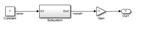
When a downstream signal originates from a block that supports signal label propagation, you can enable this option on the downstream signal line to display the propagated signal name as a label on the signal line.
For example, the output signal from the Subsystem block is configured
for signal label propagation. The propagated signal label <const>
comes from the name of the upstream Constant block output signal
const.
For more information see, Signal Label Propagation.
Tips
To display propagated signal labels for all signals, in the Simulink® Editor, on the Debug tab, select Information Overlays, then select Propagated Signal Labels.
Dependencies
The Show propagated signals property is only available for signals produced by blocks that support signal label propagation.
Programmatic Use
To configure a signal to display its propagated name programmatically, use the
set_param function to specify the
value of the ShowPropagatedSignals property for the port handle
that corresponds to the block output port that produces the signal. For an example,
see Display Propagated Signal Labels.
Parameter:
ShowPropagatedSignals |
Value:
'on' | 'off' |
Default:
'off' |
Logging and Accessibility
Select this option to mark a signal for logging. When the Signal logging option in the model configuration parameters is enabled, data for signals marked for logging is sent to the workspace and the Simulation Data Inspector during simulation. For more information, see Save Signal Data Using Signal Logging.
Programmatic Use
You can control whether to log a signal programmatically using the Simulink.sdi.markSignalForStreaming function or by using the set_param function to configure the DataLogging
property of the port handle that corresponds to the block output port that produces
the signal.
Parameter:
DataLogging |
Value:
'on' | 'off' |
Default:
'off' |
When enabled, the signal is designated as a test point. For more information, see Configure Signals as Test Points.
Programmatic Use
To designate a signal as a test point programmatically, use the set_param function to specify the value of the
TestPoint property for the port handle that corresponds to port
that produces the signal.
Parameter:
TestPoint |
Value:
'on' | 'off' |
Default:
'off' |
Specify a name for the logged signal data. By default, logged signal data uses the name of the signal specified in the model.
To specify a logging name for a signal that is different from the name of the signal
in the model, select Custom and specify the logging name in
the text box.
Dependencies
To enable the Logging Name property, select Log signal data.
Programmatic Use
To specify the logging name programmatically, use the set_param function to configure the
DataLoggingNameMode and DataLoggingName
parameters for the port handle that corresponds to the block output port that produces
the signal.
Parameter:
DataLoggingNameMode |
Value:
'SignalName' | 'Custom' |
Default:
'SignalName' |
Parameter:
DataLoggingName |
| Type: string | character vector |
When you only want to save or analyze the data from the end of a simulation, you can configure logging to capture only the last n signal values. Select Limit data points to last and specify the number of data points you want to log.
When you only log the last simulation values, dashboard blocks and the Simulation Data Inspector do not display data during simulation. Consider data requirements for each signal before you reduce the number of data points logged in simulation.
Limiting logged data to the last n signal values directly impacts memory allocation. When you specify this parameter, the software allocates memory upfront based on the specified value, not on the time steps generated during the simulation. For this reason, the Limit data points to last parameter is not recommended when logging an indeterminate number of time steps.
For more information, see Specify Signal Values to Log and Limit Size of Logged Data.
Dependencies
To enable the Limit data points to last property, select Log signal data.
Programmatic Use
To configure this option programmatically, use the set_param function to configure the
DataLoggingLimitDataPoints and
DataLoggingMaxPoints parameters for the port handle that
corresponds to the block output port that produces the signal.
Parameter:
DataLoggingLimitDataPoints |
Value:
'on' | 'off' |
Default:
'off' |
Parameter:
DataLoggingMaxPoints |
| Value: numeric scalar |
| Type: string | character vector |
Default:
'5000' |
When you want to reduce the effective sample rate for logged data, select
Decimation and specify the desired decimation factor in the text
box. For example, if you specify a decimation factor of 2, every
other signal value is logged.
Consider data requirements for each signal before reducing the number of data points logged in simulation. Decimation can cause aliasing if the effective sample rate is too low.
For more information, see Specify Signal Values to Log and Limit Size of Logged Data.
Dependencies
To enable the Decimation property, select Log signal data.
Programmatic Use
To configure this option programmatically, use the set_param function to configure the
DataLoggingDecimateData and
DataLoggingDecimation parameters for the port handle that
corresponds to the block output port that produces the signal.
Parameter:
DataLoggingDecimateData |
Value:
'on' | 'off' |
Default:
'off' |
Parameter:
DataLoggingDecimation |
| Value: numeric scalar |
| Type: string | character vector |
Default:
'2' |
Specify the sample time to use for logging the data for the selected signal. By
default, the logging sample time is inherited (-1) from the block
that produces the signal. For continuous logging sample time, specify the value as
0. To use a discrete sample time for logging data, specify the
sampling interval as a scalar.
Setting the sample time for a logged signal in the Signal Properties dialog box:
Separates design and testing because you do not need to insert a Rate Transition block to have a consistent sample time for logged signals
Reduces the amount of logged data for a continuous time signal, for which setting decimation is not relevant
Eliminates the need to post-process logged signal data for signals with different sample times
When you mark a signal for logging, the software inserts a hidden To Workspace block. When you specify a sample time for a logged signal, the software inserts a hidden Rate Transition block and a hidden To Workspace block.
Specifying a logging sample time may add a new sample time to the model. When you specify a logging sample time, the model calculates a value for the exact time hits. When you use a fixed-step solver, the logging sample time you specify must be a multiple of the base rate for the model.
Specifying a sample time for signal logging does not affect the simulation result. However, it is possible that the signal logging output for a logged signal varies depending on whether you specify a sample rate. For example, the interpolation method can differ depending on whether you specify a sample time for signal logging.
If you simulate in software-in-the-loop (SIL) mode, signal logging ignores the sample time you specify for logged signals.
Do not specify a sample time for:
Frame-based signals
Signals inside conditional subsystems or conditional referenced models
The Sample time property is the same as the Logging sample time property you configure using the Instrumentation Properties dialog box.
Dependencies
To enable the Sample time property, select Log signal data.
Programmatic Use
To configure this option programmatically, use the set_param function to configure
theDataLoggingSampleTime parameter for the port handle that
corresponds to the block output port that produces the signal.
Parameter:
DataLoggingSampleTime |
| Value: numeric scalar |
| Type: string | character vector |
Default:
'-1' |
Documentation
You can provide a description of the signal that shows in the Info tab of the Property Inspector when the signal is selected.
The description specified in the Signal Properties dialog box does not appear in
generated code. To provide a signal description that becomes a comment in generated
code, use a Simulink.Signal object.
Programmatic Use
To configure this option programmatically, use the set_param function to configure theDescription
parameter for the port handle that corresponds to the block output port that produces
the signal.
Parameter:
Description |
| Type: string | character vector |
Specify a MATLAB expression that opens documentation for the signal. For example, you can
call the web function to open an HTML file. When you
specify a value for the Document link property, you can click the
Document link field label to open the document.
Programmatic Use
To programmatically specify a document link, use the set_param property to specify the DocumentLink
property of the port handle that corresponds to the block output port that produces
the signal.
Parameter:
DocumentLink |
| Type: string | character vector |
Version History
Introduced before R2006a