convertToFrames
Concatenate data processed as frames into sequential samples for viewing in Simulation Data Inspector
Since R2021b
Syntax
Description
convertToFrames( removes frame
buffering from the signal corresponding to the sigObj)Simulink.sdi.Signal object
sigObj, which contains data processed as frames.
convertToFrames concatenates data into sequential samples, resulting
in a signal you can analyze over the duration of the simulation instead of frame by frame.
For example, suppose sigObj is processed as a two-channel signal
consisting of 200 frames of 64 samples each. The convertToFrames
function concatenates the 200 frames into a two-channel signal containing 12800 evenly
spaced samples. You can view the converted signal in the Simulation Data Inspector in a time
plot or sparklines plot.
To convert the representation of a signal using the convertToFrames
function, the signal must have a discrete sample rate, and the sample values must be
nonscalar with fixed dimensions.
Examples
Some applications buffer several samples of a signal into a frame to process with a single computation. When you log a signal that has been processed in frames to the Simulation Data Inspector, you can view and analyze the data for each frame using an array plot. To analyze the data for the signal over the duration of the simulation instead of frame by frame, you can use convertToFrames.
Simulating the model for this example requires a license for DSP System Toolbox™. Using convertToFrames or viewing the data in the Simulation Data Inspector does not require a license for DSP System Toolbox.
The LowpassFiltering model uses a Lowpass Filter block to filter a noisy, sinusoidal signal. The model uses frame-based processing with a frame size of 256 and logs two signals, Noisy Signal and Filtered Signal. Simulate the model.
out = sim("LowpassFiltering.slx");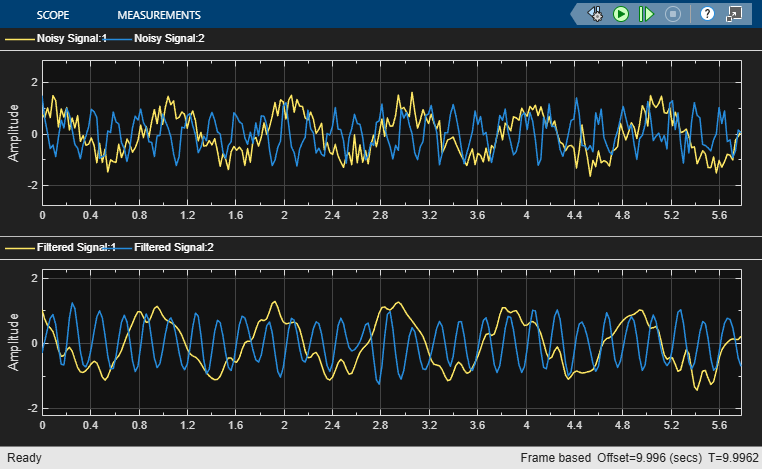
To access simulation data, get the Simulink.sdi.Run object for the current run using Simulink.sdi.getCurrentSimulationRun.
runObj = Simulink.sdi.getCurrentSimulationRun("LowpassFiltering");Access the Simulink.sdi.Signal object for the signal named Noisy Signal using getSignalsByName.
noisySig = getSignalsByName(runObj,"Noisy Signal");Check the dimensions of the signal.
size(noisySig.Values.Data)
ans = 1×3

         256           2        1723
The signal has two channels with 1723 frames at a frame size of 256. The data is organized such that the first value in the second frame is exactly 256 sample times after the first value in the first frame.
To analyze the data for the signal over the duration of the simulation instead of frame by frame, use convertToFrames. The convertToFrames function removes the buffering from each frame and allows you to visualize the data as if the model used sample-based processing.
convertToFrames(noisySig);
Check the dimensions of the signal.
size(noisySig.Values.Data)
ans = 1×2

      441088           2
After conversion, each sample is a 1-by-2 vector, reflecting the 2 channels at a particular sample time.
Because the converted signal has two elements at each sample time, the Simulation Data Inspector automatically displays the multidimensional data as a set channels in the signal table. When there are five or more channels in a frame, the Simulation Data Inspector displays the converted multidimensional data as a single signal with multidimensional sample values. To view the data as a set of channels, in the signal table, click the signal dimension and select Convert to Channels. For more information, see Convert Representation of Multidimensional Data.
To access the Signal objects for each channel, use the Children property of the original Signal object.
noisyChannel1 = noisySig.Children(1);
noisyChannel1.Name
ans =
'Noisy Signal(1)'
noisyChannel2 = noisySig.Children(2);
noisyChannel2.Name
ans =
'Noisy Signal(2)'
Each channel has scalar sample values.
size(noisyChannel1.Values.Data(1,:))
ans = 1×2

     1     1
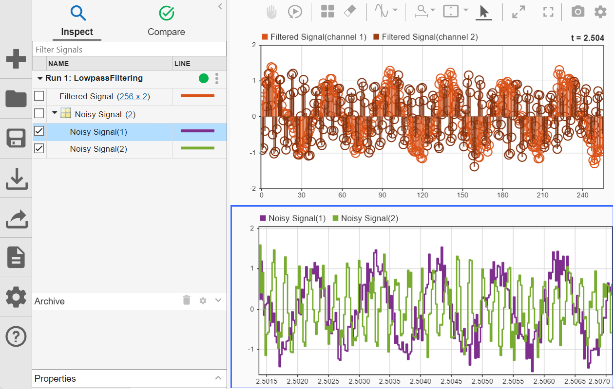
To see how the convertToFrames function changes how the Simulation Data Inspector interprets the data, plot the Noisy Signal and Filtered Signal signals. Filtered Signal, which has not been converted, can be visualized using an array plot. Noisy Signal consists of the two channels of 441088 samples across the full simulation time and can be visualized using a time plot or a sparklines plot. To view a portion of Noisy Signal data that aligns with a frame of Filtered Signal, set the time span of the time plot to the frame period value and use cursors to explore the data.
Input Arguments
Limitations
The
convertToFramesfunction does not support variable-size signals.The Simulation Data Inspector does not support converting frames for imported data.
You cannot convert a parent signal of for-each iterations to frames.
Version History
Introduced in R2021b
See Also
Objects
Functions
Topics
- Sample- and Frame-Based Concepts (DSP System Toolbox)
- Inspect Sample and Frame Rates in Simulink (DSP System Toolbox)