Simulink DateTime
R2026bSimulink® DateTime allows you to represent absolute calendar time, time standards, and epoch-based time in your model during simulation. This capability lets you model systems that depend on real-world time references, such as navigation, communication, and aerospace applications. You can:
Represent and manipulate absolute date and time values in Simulink signals.
Convert among multiple time standards, such as UTC an TAI.
Account for leap seconds in time-critical simulations.
Map simulation time to real-world calendar dates.
This table lists the Simulink DateTime blocks.
| Description | Block |
|---|---|
Output current simulation calendar date and time as
| |
Convert time points or storage data types of | |
Convert between DateTime time standards | |
Convert DateTime signal to calendar time format | |
Convert | |
Extract value of | |
Output |
Simulink blocks might use Simulink.DateTimeType objects to specify the
time point, time standard, and storage data type of DateTime signals.
Simulink DateTime Concepts
This table lists concepts and terminology for Simulink DateTime.
| Term | Definition |
|---|---|
Calendar time | DateTime representation year, month, day, hour, minute, second. |
Epoch | Reference point in time from which elapsed time is measured, for example, seconds since Unix epoch (1970-01-01T00:00:00 UTC). |
Epoch time | DateTime representation expressed as elapsed time since a defined epoch. |
Leap second | One-second adjustment occasionally applied to UTC to maintain alignment with Earth rotation. Simulink DateTime models handle leap seconds explicitly because these seconds affect conversions between UTC and continuous time standards (TAI).
|
Time representation | A DateTime value encodes the elapsed time from a reference epoch, which you can configure based on your application domain.
|
Time standard | Defines the rules for measuring the passage of time. Simulink DateTime supports multiple time standards and provides conversion between them.
You convert between time standards using the DateTime Time Standard Converter block. |
Time zone | Regional offset from UTC used to express local civil time. Time zone handling allows you to express DateTime values in local time. Design considerations include daylight saving time transitions and the relationship between time zones and UTC offsets. |
DateTime Type
DateTime blocks create and use DateTimeType data types as needed, for
example, when a block outputs a DateTime signal. Simulink blocks might use
Simulink.DateTimeType objects to specify the time point, time standard,
and storage data type of DateTime signals. On signal lines, DateTime
signals appear as datetime(timeStandard).
To create DateTime data types for blocks that support DateTime, you
can:
Use the DateTime Clock block.
To convert another signal to a
DateTimetype, use the To DateTime block
Relationship to MATLAB datetime Data
While datetime data operates in the MATLAB® workspace, Simulink DateTime provides an in-model representation suitable for signal flow, code
generation, and real-time execution.
The Simulink DateTime blocks work with MATLAB
datetime data with the DateTime Clock block and the
Date and time at
simulation time zero configuration parameter.
Date and time at simulation time zero model configuration parameter — To specify the date and time at simulation time zero at the model level using the
datetimeobject, set the Date and time at simulation time zero model configuration parameter. If the block Date and time at simulation time zero value differs from the value of the Date and time at simulation time zero model configuration parameter, the block value takes precedence.DateTime Clock block — To set the date and time at simulation time zero at the block level, set the Initial date and time source parameter to
Specify value. And then, In the Date and time at simulation time zero parameter, specify thedatetimeobject. If the block Date and time at simulation time zero value differs from the value of the Date and time at simulation time zero model configuration parameter, the block value takes precedence.Simulink converts MATLAB
datetimedata to the configured DateTime representation of the model.When loading
timeseriesinput data withdatetimerow times, interpolation must be turned off.
Simulink Blocks That Support DateTime Data Types
These blocks support DateTime data types:
You can assign DateTime-specific data types to signals in Simulink models. These types carry time standard and epoch metadata alongside the
numeric value. To create DateTime data types, use the
Simulink.DateTimeType object.
Signal Representation
DateTime signals in Simulink carry the time value and associated metadata.
UTC signals might combine the datetime numeric value with a leap second indicator to unambiguously represent times during or near a leap second event.
This composite representation enables 23:59:60 to be distinguished from 00:00:00 of the next day.
Rounding Timestamp Values
Simulink DateTime blocks always round timestamps, including negative timestamps, down using the concept of floor rounding. Floor rounding is the act of taking the largest value that is less than or equal to the original value. Applying this concept, at time t = -4.5 seconds with respect to midnight, a clock with second precision reads 11:59:55 PM.
DateTime Signals
To introduce DateTime values into your model, use a DateTime Clock block
or load datetime data from the MATLAB workspace.
The DateTime Clock block generates a continuously advancing
DateTimesignal.You can supply DateTime values through input ports using MATLAB
datetimedata stored in atimeseriesortimetable.
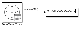
Use the DateTime Clock block to create DateTime signals
and have the Display block display the output. In this model, the
Date and time at simulation time zero parameter of the
DateTime Clock block is set to
datetime(2000,1,1,0,0,0).
Manipulate DateTime Values
Common operations on DateTime values include:
Convert between time standards — Use the DateTime Time Standard Converter block to transform DateTime values among supported time standards, including UTC, TAI, and TT.
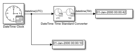
Use the DateTime Clock block to create
DateTimesignals and have the DateTime Standard Converter block convert theDateTimeUTC signal to a TAI signal. In this model:The Date and time at simulation time zero parameter of the DateTime Clock block is set to
datetime(2000,1,1,0,0,0).The Account for new leap seconds after simulation start parameter of the DateTime Clock block is cleared.
The Sample time parameter of the DateTime Clock block is set to
1for discrete behavior.The Time standard conversion parameter of the DateTime Time Standard Converter block is set to
UTC to TAI.
Extract
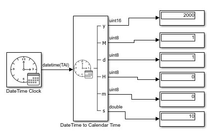
DateTimesignal to calendar components — To extract year, month, day, hour, minute, and second from aDateTimesignal, use the DateTime to Calendar Time block.Use the DateTime Clock block to create
DateTimesignals and have the DateTime to Calendar Time block extract the calendar components from theDateTimesignal. In this model:The Date and time at simulation time zero parameter of the DateTime Clock block is set to
datetime(2000,1,1,0,0,0).The Account for new leap seconds after simulation start parameter of the DateTime Clock block is cleared.
The Sample time parameter of the DateTime Clock block is set to
1for discrete behavior.Connect the DateTime to Calendar Time block output ports to multiple Display blocks, one per output port.
Format
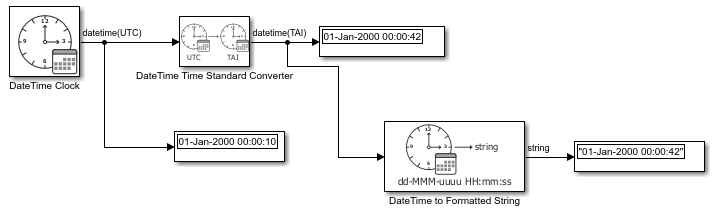
DateTimesignal as strings — To displayDateTimesignals as time strings, use the DateTime to Formatted String block.To the previous DateTime Standard Converter model, add DateTime to Formatted String block and Display blocks.
Logging
You can log DateTime signals to the MATLAB workspace as MATLAB
datetime data stored in a timeseries or
timetable. The row times of a logged timetable
represent simulation times, while DateTime signals appear as data columns
of type datetime.
Visualization with Scopes
When visualizing DateTime signals on Scope blocks,
simulations that use DateTime can be visualized on scopes with
calendar-formatted time values on the T-axis.
Loading Data
Simulink DateTime supports root inport loading.
Log, Load, and Visualize DateTime Data
This example shows how to log, load, and visualize DateTime signals in Simulink.
Visualize and Log DateTime Data From Simulation
Load model ex_datetime_generate_data.slx. Set model configuration parameter Date and time at simulation time zero to July 19, 2026.
modelA = 'ex_datetime_generate_data';
open_system(modelA)
set_param(modelA, 'DateTimeAtSimulationTimeZero', 'datetime(2026,7,19,TimeStandard=''UTC'')');
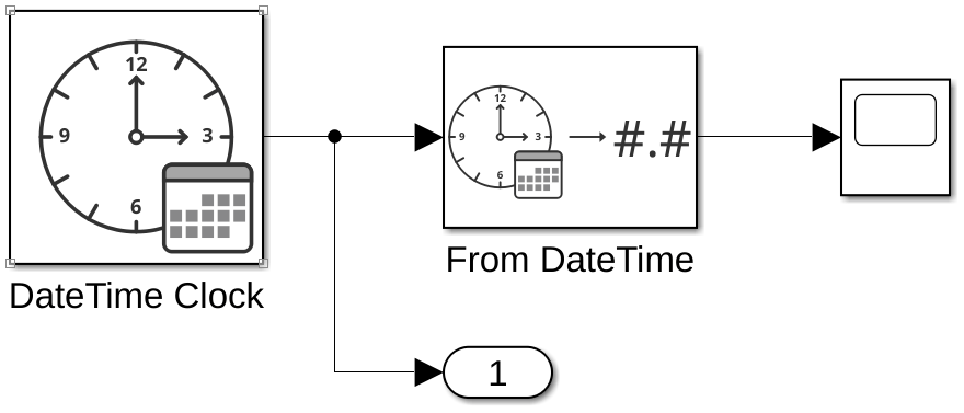
Run the model and examine the output data in the Scope. The DateTime Clock block outputs a Julian date whose day number increases by 1 over the course of the simulation. The Scope plots the DateTime signal using its stored value, which is the numerical value of the Julian date. The Scope T-Axis is labeled with dates and times starting at July 19, 2026.
out = sim(modelA);
open_system([modelA '/Scope'])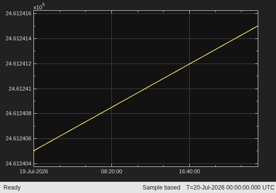
Save the logged output data to a new workspace variable and examine it. The data is logged as a timeseries of MATLAB datetime objects.
ts_data = out.yout{1}.Values timeseries
Common Properties:
Name: ''
Time: [51x1 double]
TimeInfo: [1x1 tsdata.timemetadata]
Data: [51x1 datetime]
DataInfo: [1x1 tsdata.datametadata]
More properties, Methods
Load DateTime Data in Another Model and Visualize It
Load model ex_datetime_compare_data.slx. Set model configuration parameter Date and time at simulation time zero to July 20, 2026.
modelB = 'ex_datetime_compare_data';
open_system(modelB)
set_param(modelB, 'DateTimeAtSimulationTimeZero', 'datetime(2026,7,20,TimeStandard=''UTC'')');
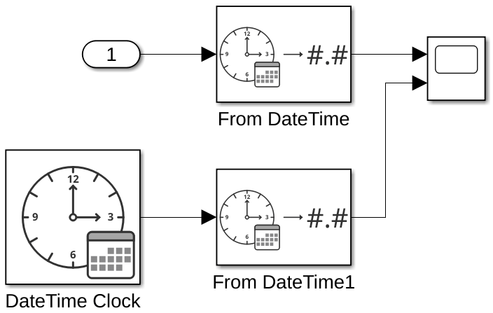
Configure the model root input port to load the logged workspace data of the previous model.
set_param(modelB, 'LoadExternalInput', 'on', 'ExternalInput', 'ts_data');
Run the model and examine both output signals in the Scope. The two plotted Julian date signals differ in stored value by exactly 1. The Scope T-Axis is labeled with dates and times starting at July 20, 2026.
sim(modelB);
open_system([modelB '/Scope'])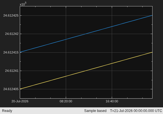
Bus and Structure Integration
You can include DateTime values as elements in Simulink bus signals and structures.
A bus element can have a
DateTimedata type.In generated code, DateTime bus elements map to structure fields with the appropriate storage type.
Replace DateTime Clock Block with System Time Call
This example shows how to use a code replacement library (CRL) entry to replace a DateTime Clock block with a call to system time provided by the C <time.h> header.
Prepare Model
Open model ex_datetimeclock_crl_harness.slx. This model uses an ERT-based system target file, and it includes a Model block configured for SIL simulation. The referenced model ex_datetimeclock_crl_model.slx contains the DateTime Clock block to be replaced by a call to the systemTime function in the generated code.
topModel = 'ex_datetimeclock_crl_harness';
botModel = 'ex_datetimeclock_crl_model';
open_system(topModel)
load_system(botModel)
Examine C Implementation
Examine the provided C implementation of the systemTime function.
type systemTime.h/* Copyright 2026 The MathWorks, Inc. */ int systemTime();
type systemTime.c/* Copyright 2026 The MathWorks, Inc. */
#include "systemTime.h"
#include <time.h>
int systemTime()
{
return time(NULL);
}
Prepare Code Replacement Library
Examine the code replacement library, which is created in crl_datetimeclock_systemtime.m and registered in rtwTargetInfo.m. The entry in the library specifies the getDateTime key and the types of two input arguments. u1 is an int32 that contains the block's output at simulation time 0, while u2 is a double that contains the current simulation time. Both arguments are ignored by the systemTime implementation. The entry also specifies the block TimePoint and TimeStandard to match by setting those algorithm parameters.
type crl_datetimeclock_systemtime.mfunction hLib = crl_datetimeclock_systemtime
% CRL_DATETIMECLOCK_SYSTEMTIME - Create a Code Replacement Library entry
% to replace a DateTime Clock block with a call to system time from the C
% <time> library.
% Copyright 2026 The MathWorks, Inc.
hLib = RTW.TflTable;
hEnt = createCRLEntry(hLib, ...
'int32 y1 = getDateTime(int32 u1, double u2)', ...
'int32 y1 = systemTime()');
hEnt.setTflCFunctionEntryParameters( ...
'Priority', 100, ...
'ImplementationHeaderFile', 'systemTime.h', ...
'ImplementationHeaderPath', '.', ...
'ImplementationSourceFile', 'systemTime.c', ...
'ImplementationSourcePath', '.');
algParams = getAlgorithmParameters(hEnt);
algParams.TimePoint = 'Seconds since Unix epoch';
algParams.TimeStandard = 'UTC';
setAlgorithmParameters(hEnt, algParams);
hLib.addEntry(hEnt);
end
if isfile("rtwTargetInfo.m")
    delete rtwTargetInfo.m
end
copyfile DateTimeClockRtwTargetInfo.txt rtwTargetInfo.m
type rtwTargetInfo.m
function rtwTargetInfo(cm)

cm.registerTargetInfo(@loc_register_crl);

end

function this = loc_register_crl

% Register a code replacement library for use with ex_datetimeclock_crl_model
this(1) = RTW.TflRegistry;
this(1).Name = 'DateTime Clock CRL';
this(1).TableList = {'crl_datetimeclock_systemtime'};
this(1).BaseTfl = '';
this(1).TargetHWDeviceType = {'*'};
this(1).Description = '';

end
Add Code Replacement Library
Add the code replacement library to the referenced model and run the harness model. Ignore warnings caused by unsaved model changes.
set_param(botModel, 'CodeReplacementLibrary', 'DateTime Clock CRL');
warning('off', 'Simulink:slbuild:unsavedMdlRefsAllowed')
sl_refresh_customizations;
simout = sim(topModel);
### Searching for referenced models in model 'ex_datetimeclock_crl_harness'.
### Total of 1 models to build.
### Starting serial code generation build.
### Starting model reference code generation target build for: ex_datetimeclock_crl_model
### Successful completion of build procedure for: ex_datetimeclock_crl_model

Build Summary

Model reference code generation targets:

Model                       Build Reason                                          Status                        Build Duration
==============================================================================================================================
ex_datetimeclock_crl_model  Target (ex_datetimeclock_crl_model.c) did not exist.  Code generated and compiled.  0h 0m 6.1239s

1 of 1 models built (0 models already up to date)
Build duration: 0h 0m 7.3431s
### Preparing to start SIL simulation ...
Building with 'gcc'.
MEX completed successfully.
### Starting SIL simulation for component: ex_datetimeclock_crl_model
### Application stopped
### Stopping SIL simulation for component: ex_datetimeclock_crl_model
Simulate and Examine Results
Compare the logged output of the Simulink model to the date and time reported by MATLAB's datetime('now') command.
tMATLAB = datetime('now', TimeStandard='UTC', Format='uuuu-MM-dd''T''HH:mm:ss''Z''');
tSimulink = datetime(simout.yout{1}.Values.Data(1), Format='uuuu-MM-dd''T''HH:mm:ss''Z''');

fprintf('MATLAB system time is %s\n', tMATLAB)
MATLAB system time is 2026-08-07T09:05:26Z
fprintf('Simulink model output is %s\n', tSimulink)Simulink model output is 2026-08-07T09:05:26Z
Limitations
The Date and time at simulation time zero configuration parameter cannot be set to a time earlier than January 1, 1972.
Simulink DateTime cannot represent data in non-UTC time zones.
Simulink does not support DateTime signals earlier than January 1, 1400 or later than December 31, 9999.
The DateTime Clock block is not supported in export-function models.
DateTime Clock blocks are not supported in subsystems that model Simulink based states in Stateflow®.
See Also
Blocks
- DateTime Clock | DateTime Data Type Converter | DateTime Time Standard Converter | DateTime to Calendar Time | DateTime to Formatted String | From DateTime | To DateTime

