Motor & Drive (System Level)
Generic motor and drive with closed-loop torque control

Libraries:
Simscape /
Electrical /
Electromechanical /
System-Level Modeling
Description
The Motor & Drive (System Level) block models a generic motor and drive or servomotor with closed-loop torque control. Use this block to model a wide range of motor types, at system-level, in traction and actuation system. The motors you can model include these brushless motors:
Permanent magnet synchronous motors (PMSMs):
Interior permanent magnet (IPM) motors or interior permanent magnet synchronous motors (IPMSMs)
Surface permanent magnet (SPM) motors or surface permanent magnet synchronous motors (SPMSMs)
Brushless direct current (BLDC) motors
Axial flux traction motors
You can also use this block to model brushed motors with closed-loop torque control using a block.
To enable fast simulation at a system level, this block abstracts the motor, drive electronics, and controls.
The block permits only the range of torques and speeds defined by the torque-speed envelope. In the default block configuration, you specify this data in the block dialog box as a set of speed data points and the corresponding maximum torque values. This figure shows the Cartesian quadrants definition:

This table shows the operating regions and the values for the speed and electromagnetic torque for each quadrant:
| Quadrant | Description | Speed | Electromagnetic Torque | Operating Mode |
|---|---|---|---|---|
| 1 | Forward motoring region | Positive | Positive | Motoring mode |
| 2 | Forward generating region | Positive | Negative | Generating mode |
| 3 | Reverse motoring region | Negative | Negative | Motoring mode |
| 4 | Reverse generating region | Negative | Positive | Generating mode |
In this table:
Motoring mode converts electrical power into mechanical power.
Generating mode converts mechanical power into electrical power.
A positive rotational velocity means the distance between ports C and R increases over time.
A negative rotational velocity means the distance between ports C and R decreases over time.
A positive torque means the torque contributes to the increase in the rotational velocity. The block produces a positive torque that acts from the mechanical C to R ports.
A negative torque contributes to reducing the rotational velocity. If the rotational velocity is already negative, a negative torque accelerates it in the negative direction.
Specify the torque-speed envelope for the positive torque region only, that is, quadrants 1 and 4. The torque-speed envelope for the motor has the same profile when the motor operates in a reverse direction, which is represented by quadrants 2 and 3. If you specify the envelope only for positive speeds, then the block defines the quadrant 4 torque envelope as the mirror image of quadrant 1. This figure shows a typical torque-speed envelope for a torque-controlled motor and drive:
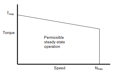
Instead of providing tabulated torque-speed data, you can specify the maximum torque and maximum power. This figure shows the resulting torque-speed envelope profile in quadrant 1. The same profile constrains the other three operating quadrants.

The Visualize Four-Quadrant Operation of Electric Drive System example helps you visualize the torque-speed trajectory of the Motor & Drive (System Level) block operated in all four quadrants.
Note
Simscape™ Electrical™ includes several blocks that can model the same type of motor or actuator. Choose a block that has sufficient modeling detail for the engineering design questions that you need to answer. Do not use a block that has more modeling detail than you need, because higher-fidelity models slow down simulation and are more complex to parameterize.
Blocks like the Motor & Drive (System Level) block use energy balancing or other abstraction methods. These models have a low level of fidelity. Use this block when you need a long simulation time, for example, to analyze drive cycles for electric vehicles. For more information about choosing the right block to model your motor at the right level of fidelity, see Choose Blocks to Model Motors or Actuators.
Intermittent Over-Torque Operation
To over-torque the motor for short periods of time, set the Allow
intermittent over-torque parameter to Yes.
In this case, you must specify the values for both the Continuous
operation maximum torque envelope and the Intermittent
operation maximum torque envelope parameters. Internally the block
determines which torque envelope to apply based on the torque demand history. You
can over-torque the motor drive if the torque demand has been less than the
continuous operation torque envelope for more than the value specified in the
Recovery time parameter. Over-torquing is disabled if
over-torquing has been applied for longer than the value specified in the
Over-torque time limit parameter.
For more application specific management of over-torquing, disable the over-torquing in the Motor & Drive block and externally implement the torque limiting in Simulink® between the torque demand and the torque reference input port, Tr, of the Motor & Drive block.
Model Electrical Losses
The block allows both simplified and tabulated definition of electrical losses. The default, simplified, behavior is to model the losses as the sum of the following four terms:
A series resistance between the DC power supply and the motor drive.
Fixed losses independent of torque and speed, P0. Use this to account for fixed converter losses.
A torque-dependent electrical loss kτ2, where τ is the torque and k is a constant. This represents ohmic losses in the copper windings.
A speed-dependent electrical loss kwω2, where ω is the speed and kw is a constant. This represents iron losses due to eddy currents.
This simplification of loss dependency on torque and speed might be sufficient for early design work, regardless of the underlying motor type and drive topology.
If you require more accuracy, or later in the design process, you can provide tabulated loss values as a function of motor speed and load torque. When using this option, provide data for all of the operating quadrants that your simulation will run in. If you provide partial data (for example, just for the quadrant 1 forward motoring region), then the other quadrants are assumed to repeat the same pattern of losses. This will normally be correct for the reverse motoring region, but may be an approximation for the braking/generating quadrants. The block does no extrapolation of loss values for speed and torque magnitudes that exceed the range of the table.
Finally, you can specify electrical losses by using tabulated efficiency data, instead of a single efficiency measurement or tabulated loss data. When using this option, also provide data for all of the operating quadrants that your simulation will run in. If you provide partial data (for example, just for the quadrant 1 forward motoring region), then the other quadrants are assumed to repeat the same pattern of losses.
The best practice is to provide tabulated loss data as a function of speed and torque, rather than tabulated efficiency data, because:
Efficiency becomes ill-defined for zero speed or zero torque.
Using losses, you can also account for fixed losses that are still present for zero speed or torque.
If you use the tabulated efficiencies option:
The block converts the efficiency values you provide into losses and uses the tabulated losses for simulation.
Efficiency values you provide for zero speed or zero torque are ignored, and losses are assumed zero when either torque or speed is zero.
The block uses linear interpolation to determine losses. Provide tabulated data for low speeds and low torques, as required, to get the desired level of accuracy for lower power conditions.
The block does no extrapolation of loss values for speed and torque magnitudes that exceed the range of the table.
When you provide tabulated loss or efficiency data, you can also specify it as a function of speed, load torque, and DC supply voltage. This option is useful when the supply voltage is not regulated and can vary during the simulation. One example is an electric vehicle drivetrain that does not have a DC-DC regulator upstream of the motor drive. Use the Motor & Drive (System Level) block to model the motor drive and provide tabulated loss or efficiency values as a function of motor speed, load torque, and DC supply voltage.
Plot Efficiency Map
The block allows you to visualize the map of the torque-speed envelope and the steady-state electrical efficiency of the motor and drive. To plot the efficiency map, either:
Double-click the block in your block diagram and, in the Description tab, click
Plot efficiency map.Double-click the block in your block diagram and, in the Utilities section, click the Plot button next to the Efficiency map parameter. (since R2026a)
This efficiency map does not include the losses generated by the External supply series resistance and Rotor damping parameters.

Model Thermal Effects
You can expose the thermal port to model the effects of losses that convert power to heat. To expose the thermal port, set the Modeling option parameter to either:
No thermal port— The block does not contain a thermal port.Show thermal port— The block contains one thermal conserving port.
For more information about using thermal ports in actuator blocks, see Simulating Thermal Effects in Rotational and Translational Actuators.
Model Faults
To model a fault in the Motor & Drive (System Level) block, in the Faults section, click Add fault next to the fault that you want to model. For more information about fault modeling, see Fault Behavior Modeling and Fault Triggering.
The Motor & Drive (System Level) block allows you to model an open-circuit fault. When the fault is triggered, the servomotor stops operating, takes zero current from the supply side, and supplies zero current to the load side.
You specify how and when faults occur by using the Trigger type parameter.
If you set the Trigger type to
Timed, the Motor & Drive (System Level) block triggers faults when
the simulation time reaches the value you specify for the Trigger fault at time parameter.
If you set the Trigger
type to Conditional, you can choose whether faults
in the Motor & Drive (System Level) block are reversible (since R2025a). To model irreversible faults, click
Open fault properties to open the Property Inspector and select the
Trigger stays on once activated parameter. The block enters the faulted
state when the trigger condition becomes true for the first time and remains in the faulted
state for the rest of the simulation. To model reversible faults, clear the Trigger
stays on once activated parameter. The block enters the faulted state when the
trigger condition is true and enters the unfaulted state when the trigger condition is
false.
For more information about adding faults to blocks and specifying fault triggers, see Introduction to Simscape Faults.
Variables
To set the priority and initial target values for the block variables before simulation, use the Initial Targets section in the block dialog box or Property Inspector. For more information, see Set Priority and Initial Target for Block Variables.
Nominal values provide a way to specify the expected magnitude of a variable in a model. Using system scaling based on nominal values increases the simulation robustness. You can specify nominal values using different sources, including the Nominal Values section in the block dialog box or Property Inspector. For more information, see System Scaling by Nominal Values.
Examples
Visualize Four-Quadrant Operation of Electric Drive System
Helps you visualize the torque-speed trajectory of a Motor & Drive (System Level) block operated in all four quadrants.

Brushless DC Motor
How a system-level model of a brushless DC motor (i.e. a servomotor) can be constructed and parameterized based on datasheet information. The motor and driver are modeled as a single masked subsystem. If viewing the model in Simulink®, select the Motor and driver block, and type Ctrl+U to look under the mask and see the model structure.

Motor Torque-Speed Curves
A comparison of the torque-speed characteristics for five different motor types. To select the motor type, right-click on the Electric Motor block and select Block Parameters (Subsystem) from the context menu. In the new window, specify the desired motor using the Label mode active choice parameter. All motors have been sized for roughly the same mechanical power rating.
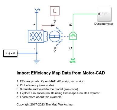
Import Efficiency Map Data from Motor-CAD
Import efficiency map data from Motor-CAD to parameterize the Simscape™ Electrical™ Motor & Drive (System Level) block. This provides fast system-level simulation capability of a motor drive whilst still making accurate predictions about losses.
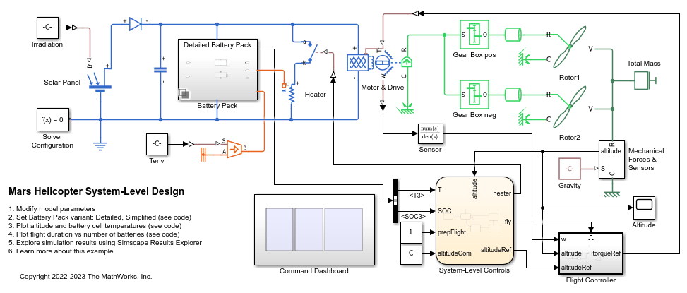
Mars Helicopter System-Level Design
Use Simscape™ Electrical™ to model a helicopter with coaxial rotors suitable to fly on Mars. This helicopter takes inspiration from Ingenuity, the robotic helicopter developed by NASA, which accomplished the first powered flight on another planet.

System-Level AC Drive
Model a system-level AC drive for an electric machine by using the AC-DC Converter (Three-Phase) block and Motor & Drive (System Level) block. The AC-DC converter represents a grid-side converter which provides a constant DC-link voltage. The Motor & Drive block acts as a generic AC electric machine with its DC-AC converter. This modeling approach provides fast system-level simulation without the switching events of the power converters.

Model a Motor Drive with Multiple Intermittent Torque Limits
Model a motor drive with multiple intermittent over-torque limits by using Simscape™ Electrical™.
Assumptions and Limitations
The motor driver tracks a torque demand with a time constant Tc.
Motor speed fluctuations due to mechanical load do not affect the motor torque tracking.
The electrical connections must always be connected to a supply, such as a DC voltage source or a battery, that provides a positive voltage and is capable of delivering or absorbing the required power. To simulate turning the supply source on and off, see Model Faults.