Simulate Architectural Behavior for Mobile Robot
To simulate the mobile robot logical architecture, link Simulink® models to the components or add Simulink subsystem components. For details, see Implement Component Behavior Using Simulink. These models act as Simulink behaviors and can be simulated in System Composer™ by clicking Run. The simulation shows how well the mobile robot follows a trajectory created by a controller to avoid an obstacle.
Note
This example uses Simscape™ blocks. If you do not have a Simscape license, you can open the model but can only make basic changes, such as modifying block parameters.
Simulate Architectural Behavior
The mobile robot example includes a logical architecture with component behaviors defined. You can run the simulation to watch the mobile robot avoid an obstacle.
Load the project.
openProject("scMobileRobotExample");Add Behavior to Logical Architecture
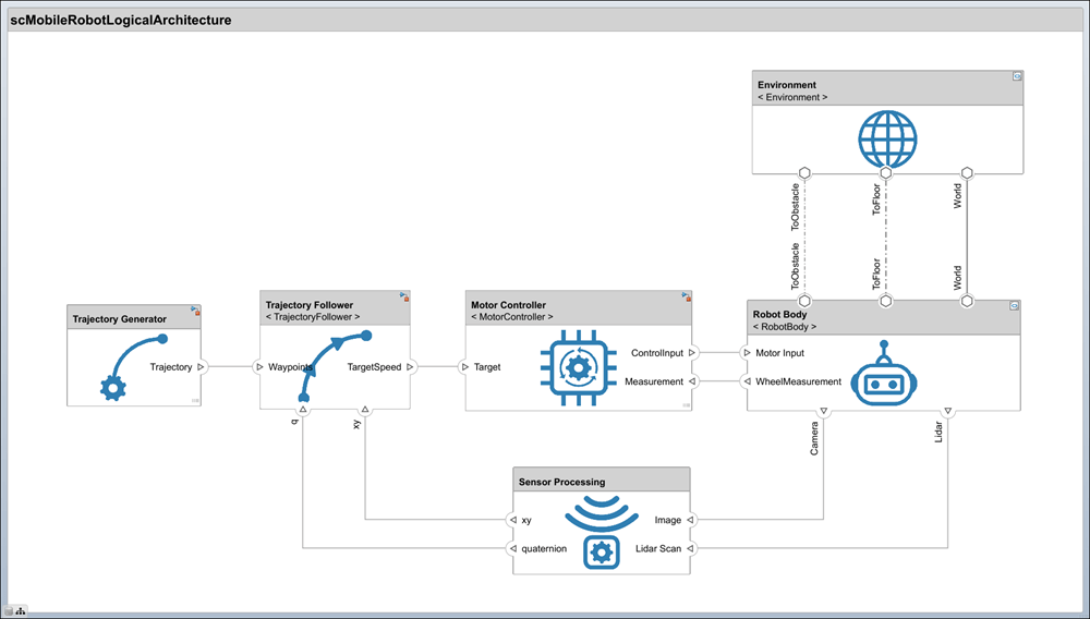
The logical architecture model describes the behavior of the mobile robot system for simulation: trajectory generator, trajectory follower, motor controller, sensor algorithm, and robot and environment. The connections represent the interactions in the system. Open the logical architecture model without any behaviors, double-click the file or run this command.
systemcomposer.openModel("scMobileRobotLogicalArchitecture_Initial");
The architecture model describes the behavior of the robot, but no behavior is actually added to the architecture yet. By adding Simulink or Stateflow® behavior, the logical architecture can also be simulated.
Create a new behavior based on the interface of a component. If a model or subsystem file already exists for the behavior, use Link To Model to link to the existing model or subsystem. To create new subsystem reference behavior for the Motor Controller component, right-click and select Create Simulink Behavior, or, on the toolstrip, click Create Simulink Behavior. For more information, see Implement Component Behavior Using Simulink.
You can create Simulink behaviors using multiple methods: Subsystem, Subsystem Reference, and Model Reference. Use Subsystem to create a subsystem component behavior that is part of the parent architecture model. Use the Subsystem Reference or Model Reference option to save the behavior as a separate artifact and reuse the behavior. Physical ports can only cross subsystem boundaries, so for physical systems, Subsystem Reference or Subsystem are recommended.
If you already have a behavior defined in a model file or subsystem file, use Link To Model to link a component to the corresponding file. On the toolstrip, click Link to Model, or right-click the Environment component and select Link to Model to link to the Environment.slx subsystem file.
Logical Architecture Model for Mobile Robot
Open the final logical architecture where behavior is added to all the components.
systemcomposer.openModel("scMobileRobotLogicalArchitecture");The Robot Body and Environment are Simulink subsystem reference components that support physical ports. The Trajectory Generator is a Simulink subsystem component that also supports physical ports. The Trajectory Follower and Motion Controller components are represented as Simulink models linked to the components as referenced models.
A behavior algorithm is created based on port information only. When designing a logical architecture, you can set the interface of the port to define the information in more detail. For example, if you know that 800 x 600 RGB images captured at 24 frames per second are transferred from the camera sensor, then you can set the corresponding port interfaces accordingly to ensure efficient data transfer. For more information about setting interfaces, see Define Port Interfaces Between Components.
Add component images to your components by selecting a component and then navigating on the toolstrip to Format > Add Image. Browse for an image from the Tools folder. Click OK.
Run Simulation Using Logical Architecture
Once behavior models are linked, you can simulate the architecture model just like any other Simulink model by clicking Run. Simulation verifies requirements such as Transportation, Collision Avoidance, and Path Generation.
sim scMobileRobotLogicalArchitecture;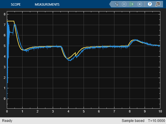
The scope from the MotorController component behavior shows how a simple P-gain controller performs to follow the reference velocity for one of the wheels on the robot.
In the Multibody Explorer (Simscape Multibody), switch to the isometric view by selecting ![]() . Watch the mobile robot avoid an obstacle.
. Watch the mobile robot avoid an obstacle.

References
[1] Rahman, Mohd Azizi Abdul, Katsuhiro Mayama, Takahiro Takasu, Akira Yasuda, and Makoto Mizukawa. “Model-Driven Development of Intelligent Mobile Robot Using Systems Modeling Language (SysML).” In Mobile Robots: Control Architectures, Bio-Interfacing, Navigation, Multi Robot Motion Planning and Operator Training, edited by Janusz Będkowski. InTech Open, 2011. https://doi.org/10.5772/26906.