wlanLinkConfig
Description
Use the wlanLinkConfig object to set the link configuration of an
        IEEE®
      802.11be™ (Wi-Fi® 7) multilink device (MLD).
Creation
Description
mldLinkCfg = wlanLinkConfig
mldLinkCfg = wlanLinkConfig( sets
          the properties of the
          link configuration object by using one or more optional name-value arguments. For example,
            Name=Value)TransmissionFormat="VHT" sets the physical layer (PHY) transmission
          format to very high throughput (VHT). 
Properties
Operating frequency band and channel number, specified as an
            N-by-2 matrix. N specifies the number of
              wlanLinkConfig objects, and must be greater than or equal to 1. The
            first value in each row is the operating frequency band, specified as 2.4, 5, or 6. The
            second value in each row is the channel number, specified according to the constraints
            in this table.
| Operating Frequency Band | Channel Number | 
|---|---|
| 2.4 | Integer in the range [1, 14] | 
| 5 | Integer in the range [1, 200] | 
| 6 | Integer in the range [1, 233] | 
When creating a wlanLinkConfig object, configure multiple links
            simultaneously by setting this property as a name-value argument. Once you create the
            object, you can configure a single wlanLinkConfig object at a time by
            setting this property.
The Valid Channel Number and Bandwidth Combinations topic describes the valid combinations of band, channel number, and channel bandwidth.
Data Types: double
PHY transmission format for unicast data frame, specified as
              "Non-HT", "HT-Mixed", "VHT",
              "HE-SU", "HE-EXT-SU", or
              "EHT-SU". The "EHT-SU" value of this property
            specifies extremely high-throughput (EHT) multiuser PHY protocol data unit (MU PPDU)
            format for a single user (SU). Note that the broadcast data frame transmissions always
            use the "Non-HT" PHY transmission format, regardless of the value of
            this property.
Data Types: char | string
Maximum bandwidth for transmission or reception in Hz, specified as
              20e6, 40e6, 80e6,
              160e6, or 320e6. The possible values for this
            property depend on the BandAndChannel and TransmissionFormat properties.
- If you set the first entry of the - BandAndChannelto- 2.4, this property supports- 20e6Hz and- 40e6Hz.
- If you set the - TransmissionFormat- "Non-HT"or- "HE-EXT-SU", this property supports only- 20e6Hz.
- If you set the - TransmissionFormatproperty to- "HT-Mixed", this property supports- 20e6Hz and- 40e6Hz.
- If you set the - TransmissionFormatproperty to- "VHT"or- "HE-SU"this property supports- 20e6Hz,- 40e6Hz,- 80e6Hz, and- 160e6Hz.
- If you set the - TransmissionFormatproperty to- "EHT-SU", this property supports all channel bandwidths.
The Valid Channel Number and Bandwidth Combinations topic describes the valid combinations of band, channel number, and channel bandwidth.
Data Types: double
Modulation and coding scheme (MCS), specified as an integer in the range [0, 13].
            For unicast data frame transmissions, the set of values that this property can take
            depends on the TransmissionFormat property.
- When - TransmissionFormatis- "Non-HT"or- "HT-Mixed", the range of values is [0, 7]. When- TransmissionFormatis- "HT-Mixed", the given value in the range [0, 7] maps to a value in the range [0, 31] using the calculation MCS + (NSTS – 1) × 8, where NSTS is the value of the- NumSpaceTimeStreamsproperty.
- When - TransmissionFormatis- "VHT", the range of values is [0, 9]. The set of possible values additionally depends on the- ChannelBandwidthand- NumSpaceTimeStreamsproperties.- When - ChannelBandwidthis- 20e6, you can set the- MCSvalue to- 9only when- NumSpaceTimeStreamsis set to- 3or- 6.
- When - ChannelBandwidthis- 80e6, the- MCSvalue- 6is not supported when you set the- NumSpaceTimeStreamsproperty to- 3or- 7. The- MCSvalue- 9is not supported when you set the- NumSpaceTimeStreamsproperty to- 6.
- When - ChannelBandwidthis- 160e6, the- MCSvalue- 9is not supported when- NumSpaceTimeStreamsis set to- 3.
 
- When - TransmissionFormatis- "HE-EXT-SU", the range of values is [0, 2].
- When - TransmissionFormatis- "HE-SU"the range of values is [0, 11].
- When - TransmissionFormatis- "EHT-SU", the range of values is [0, 13].
Note that the MCS value for broadcast data frame transmissions is always
              0, regardless of the value set for this property.
Data Types: double
Number of transmit antennas, specified as an integer in the range [1, 8]. The link uses the same number of antennas for reception.
If you specify the EnhancedMultilinkMode property of the corresponding wlanMultilinkDeviceConfig object as "EMLSR", the link
            also uses this number of antennas to listen for an initial control frame (ICF). When the
            link is active, it aggregates the NumTransmitAntennas
            values of all the links in the wlanMultilinkDeviceConfig object and
            uses this value for transmission and reception. The aggregate must be less than or equal
            to eight. An EMLSR link at a STA is active when it initiates a frame exchange sequence
            with an AP MLD or responds to an ICF to continue a frame exchange sequence initiated by
            an AP MLD. (since R2024b)
Note
- All the links operating in simultaneous transmit and receive (STR) mode in the network must have the same value for this property. 
- If an EMLSR STA has i links with - NumTransmitAntennasvalues of N1, …, Ni, its associated AP must have a- NumTransmitAntennasvalue of N1 + ⋯ + Ni for each link.
Data Types: double
Number of space-time streams, specified as an integer in the range [1, 8]. The value
            of this property must be less than or equal to the value of the NumTransmitAntennas property. If you set this value as less than the
              NumTransmitAntennas value, the node uses Fourier spatial mapping
            to transmit unicast data frames. This property is applicable only for transmitting
            unicast data frames. The number of space-time streams for broadcast data frame
            transmissions is always 1, regardless of the value of this
            property.
If you specify the EnhancedMultilinkMode property of the corresponding wlanMultilinkDeviceConfig object as "EMLSR", when the
            link is active, it aggregates the NumSpaceTimeStreams
            values of all the links in the wlanMultilinkDeviceConfig object and
            uses this value for data frame transmission.  (since R2024b)
Data Types: double
High throughput (HT) MAC protocol data unit (MPDU) aggregation selection, specified
            as a logical 1 (true) or 0
              (false). To create an aggregated MPDU (A-MPDU) by concatenating
            multiple MPDUs, set this property to true.
Dependencies
To enable this property, set the TransmissionFormat"HT-Mixed".
Data Types: logical
Maximum number of MPDUs in an A-MPDU, specified as an integer in the range [1,
            1024]. The set of values that this property can take depends on the TransmissionFormat
- When - TransmissionFormatis- "HT-Mixed"and the- AggregateHTMPDUproperty is- true, the range of values is [1, 64].
- When - TransmissionFormatis- "VHT", the range of values is [1, 64].
- When - TransmissionFormatis- "HE-SU"or- "HE-EXT-SU", the range of values is [1, 256].
- When - TransmissionFormatis- "EHT-SU", the range of values is [1, 1024].
This property does not apply when TransmissionFormat is
              "Non-HT", or when TransmissionFormat is
              "HT-Mixed" and AggregateHTMPDU is
              false.
Note
All MLDs in the network must have the same value for this property.
Data Types: double
Threshold for RTS transmission, specified as an integer in the range [0, 6500631]. If the size of a MAC frame exceeds the value of this property, the node uses the request to send/clear to send (RTS/CTS) mechanism.
Dependencies
To enable this property, set the DisableRTSfalse.
Data Types: double
RTS/CTS mechanism selection, specified as a logical 0
              (false) or 1 (true). To
            disable the RTS/CTS mechanism in the simulation, set this property to
              1 or true.
This property does not apply to multi-user request to send (MU-RTS) ICF transmissions from an AP to an EMLSR STA.
Data Types: logical
Disable acknowledgements selection, specified as a logical 0
              (false) or 1 (true). To
            disable the transmission of acknowledgements in response to data frames, set this
            property to 1 or true.
Data Types: logical
Minimum range of the contention window for the four access categories (ACs), specified as a four-element vector of integers in the range [1, 1023]. The four entries are the minimum ranges, in slots, for the Best Effort, Background, Video, and Voice ACs, respectively.
Maximum range of the contention window for the four ACs, specified as a four-element vector of integers in the range [1, 1023]. The four entries are the maximum ranges, in slots, for the Best Effort, Background, Video, and Voice ACs, respectively.
Arbitrary interframe space values for the four ACs, specified as a four-element vector of integers in the range [1, 15]. The entries of the vector represent the AIFS values, in slots, for the Best Effort, Background, Video, and Voice ACs, respectively.
- If the - Modeproperty of the- wlanMultilinkDeviceConfigobject is- "AP", each element of this vector must be in the range [1, 15].
- If the - Modeproperty of the- wlanMultilinkDeviceConfigobject is- "STA", each element of this vector must be in the range [2, 15].
Transmission opportunity (TXOP) duration limit, specified as a vector of four
            integers in the range [0, 1023]. The four integers are the TXOP limit values for the
            Best Effort, Background, Video, and Voice ACs, respectively. The limits are in units of
            32 microseconds. If you specify a vector element as 0, the object
            disables multiple frame transmissions within a TXOP for the AC that corresponds to that
            element.
Note
The value of this property must be [0 0 0 0] in these cases:
- You specify the - TransmissionFormatproperty as- "Non-HT".
- You specify the - TransmissionFormatproperty as- "HT-Mixed"and the- AggregateHTMPDUproperty as- false.
Control frames rate of 6 Mb/s, specified as a logical 0
              (false) or 1 (true). To use a
            data rate of 6 Mb/s for control frames, set this property to 1 or
              true.
Data Types: logical
Non-HT data rates supported in the basic service set (BSS), specified as a vector
            that is a subset of these values: [6 9 12 18 24 36 48 54]. The
            mandatory data rates are 6, 12, and
              24. The stations associated with an AP use the same basic rates as
            the AP.
Dependencies
To enable this property, set the Mode property of the wlanMultilinkDeviceConfig object to "AP".
Data Types: double
Transmit power in dBm, specified as a real scalar.
Data Types: double
Transmit gain in dB, specified as a real scalar.
Data Types: double
Receive gain in dB, specified as a real scalar.
Data Types: double
Receiver noise figure in dB, specified as a nonnegative scalar.
Data Types: double
Beacon interval in TU, specified as an integer in the range [1, 254]. A TU is a
            measurement of time equal to 1024 microseconds. At the end of each beacon interval, the
            beacon frames contend for medium access by using the voice access category. The MAC
            internally sets the service set identifier (SSID) in a beacon frame to
              "WLAN". To differentiate beacons of different APs in a packet
            analyzer tool, such as Wireshark, use the MAC address of the AP transmitting the beacon. 
Dependencies
To enable this property, set the Mode property of the wlanMultilinkDeviceConfig object to "AP".
Data Types: double
Time offset specified for the first beacon transmission in TUs, specified as a nonnegative integer or a nonnegative vector of form [MinTimeOffset MaxTimeOffset]. A TU is a measurement of time equal to 1024 microseconds.
- If you specify this value as a scalar, this object assigns this value to the initial time offset. 
- If you specify this value as a vector, this object assigns a random initial time offset between MinTimeOffset and MaxTimeOffset. MinTimeOffset must be less than MaxTimeOffset. 
Each element of this property must be an integer in the range [0, 254].
            If you enable beacon transmission, the default value is [0,
                . Otherwise, the default property is
            an empty array (BeaconInterval][]).
Dependencies
To enable this property, set the Mode property of the wlanMultilinkDeviceConfig object to "AP" and the
                BeaconInterval property of the wlanLinkConfig object to
              a finite value.
Data Types: double
Since R2025a
Type of interference modeling, specified as "co-channel",
              "overlapping-adjacent-channel", or
              "non-overlapping-adjacent-channel".
- "co-channel"— If you set this property to- "co-channel", the object considers signals with the same center frequency and bandwidth as the receiver to be signals of interest (SOIs) and interference.
- "overlapping-adjacent-channel"— If you set this property to- "overlapping-adjacent-channel", in addition to signals that satisfy the conditions described for- "co-channel", the object makes these additional considerations:- Signals that satisfy these conditions are SOIs: - One of the 20 MHz subchannels that receives the signal aligns with the primary 20 MHz of the receiver. 
- Bandwidth of the signal is less than or equal to the operating bandwidth of the receiver. 
 
- Signals that overlap in frequency with the frequency range of the receiver operation are interference. 
 
- "non-overlapping-adjacent-channel"— If you set this property to- "non-overlapping-adjacent-channel", in addition to signals that satisfy the conditions described for- "co-channel"and- "overlapping-adjacent-channel", the object makes this additional consideration:- Signals that overlap with frequencies in the range [f1 – fd, f2 + fd] are interference. f1 and f2 are the starting and ending frequencies of receiver operation, respectively. fd is the value of the - MaxInterferenceOffsetproperty.
 
In networks where nodes operate in channels and bandwidths that cause partial
            frequency overlap, specify this property as
              "overlapping-adjacent-channel" or
              "non-overlapping-adjacent-channel".
Dependencies
Abstract PHY simulations do not support modeling adjacent channel interference. To
              specify this property as "overlapping-adjacent-channel" or
                "non-overlapping-adjacent-channel", you must specify the
                PHYAbstractionMethod property of the wlanNode object as
                "none". 
Data Types: char | string
Since R2025a
Maximum frequency offset for determining interference, specified as a nonnegative
            scalar. Frequency is measured in Hz. This property specifies the offset between the edge
            of the receiver operating frequency and the edge of the interfering signal. If you
            specify this property as Inf, the object considers all signals that
            overlap in time to be interference, regardless of their frequency. If you specify this
            property as a nonnegative finite scalar, the object considers signals that overlap with
            the SOI in time and with the interval [f1 –
              MaxInterferenceOffset,
              f2 + MaxInterferenceOffset] in frequency to be interference.
              f1 and
              f2 are starting and ending frequencies of
            the receiver operation, respectively. 
Dependencies
To enable this property, set the InterferenceModeling property to
                "non-overlapping-adjacent-channel".
Data Types: double | single
Since R2025a
Index of primary 20 MHz channel, specified as an integer in the range [1,
              MaxPrimaryChannelIndex]. MaxPrimaryChannelIndex
            is the maximum number of 20 MHz channels that can be present in the channel bandwidth.
            This table shows how the MaxPrimaryChannelIndex value depends on the
              ChannelBandwidth value.
| 
 | 
 | 
|---|---|
| 
 | 
 | 
| 
 | 
 | 
| 
 | 
 | 
| 
 | 
 | 
If you specify the ChannelBandwidth value as
              20e6, the value of this property is 1. Note that
            the indexing of the primary 20 MHz channel starts from the lowest 20 MHz
            subchannel.
Dependencies
To enable this property, set the Mode
              property of the corresponding wlanMultilinkDeviceConfig object to "AP" and the
                ChannelBandwidth property to a value greater than
                20e6.
Data Types: double
This property is read-only.
Channel center frequency in Hz, specified as a numeric scalar. This value specifies
            the operating center frequency of the link corresponding to the value that you set using
            the BandAndChannel property.
Data Types: double
Examples
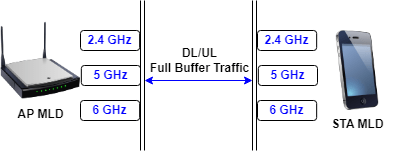
Simulate an IEEE 802.11b (Wi-Fi 7) multilink operation (MLO) in the 2.4 GHz, 5 GHz, and 6 GHz bands.
Using this example, you can:
- Create an 802.11be network consisting of an access point (AP) MLD and a station (STA) MLD. 
- Configure the AP MLD and STA MLD to operate in the 2.4 GHz, 5 GHz, and 6 GHz bands. 
- Associate the STA MLD with the AP MLD, and add full buffer downlink (DL) and uplink (UL) application traffic between them. 
- Simulate the network and get the statistics. 
The example creates, configures, and simulates this scenario.

Check if the Communications Toolbox™ Wireless Network Simulation Library support package is installed. If the support package is not installed, MATLAB® returns an error with a link to download and install the support package.
wirelessnetworkSupportPackageCheck
Specify the simulation time in seconds. Initialize the wireless network simulator
simulationTime = 1; networkSimulator = wirelessNetworkSimulator.init;
Create an MLD link configuration object, specifying the operating frequency bands as 2.4 GHz, 5 GHz and 6 GHz.
mldLinkCfg = wlanLinkConfig(BandAndChannel=[2.4 6; 5 36; 6 1]);
Create a WLAN node with an AP MLD configuration.
mldAccessPointCfg = wlanMultilinkDeviceConfig(Mode="AP",LinkConfig=mldLinkCfg); mldAccessPointNode = wlanNode(Name="AP",DeviceConfig=mldAccessPointCfg)
mldAccessPointNode = 
  wlanNode with properties:
                    Name: "AP"
                Position: [0 0 0]
   Read-only properties:
     MACFrameAbstraction: 1
    PHYAbstractionMethod: "tgax-evaluation-methodology"
            DeviceConfig: [1×1 wlanMultilinkDeviceConfig]
                      ID: 1
Create a WLAN node with an STA MLD configuration.
mldStationCfg = wlanMultilinkDeviceConfig(Mode="STA",LinkConfig=mldLinkCfg); mldStationNode = wlanNode(Name="STA",DeviceConfig=mldStationCfg)
mldStationNode = 
  wlanNode with properties:
                    Name: "STA"
                Position: [0 0 0]
   Read-only properties:
     MACFrameAbstraction: 1
    PHYAbstractionMethod: "tgax-evaluation-methodology"
            DeviceConfig: [1×1 wlanMultilinkDeviceConfig]
                      ID: 2
Associate the STA MLD with the AP MLD, and add full buffer DL and UL application traffic between them.
associateStations(mldAccessPointNode,mldStationNode,FullBufferTraffic="on")Add the nodes to the wireless network simulator.
addNodes(networkSimulator,[mldAccessPointNode mldStationNode])
Run the network simulation for the specified simulation time.
run(networkSimulator,simulationTime)
Retrieve and display statistics of the AP MLD and STA MLD. For more information about the MLO statistics, see WLAN System-Level Simulation Statistics.
mldAccessPointStats = statistics(mldAccessPointNode)
mldAccessPointStats = struct with fields:
    Name: "AP"
      ID: 1
     App: [1×1 struct]
     MAC: [1×1 struct]
     PHY: [1×1 struct]
    Mesh: [1×1 struct]
mldStationStats = statistics(mldStationNode)
mldStationStats = struct with fields:
    Name: "STA"
      ID: 2
     App: [1×1 struct]
     MAC: [1×1 struct]
     PHY: [1×1 struct]
    Mesh: [1×1 struct]
Version History
Introduced in R2024aThe new InterferenceModeling and MaxInterferenceOffset properties enable you to model adjacent channel
        interference.
The new PrimaryChannelIndex property enables you to configure the index of the primary
        20 MHz channel.
You can now transmit multiple data frames within a single transmission opportunity
        (TXOP). To use this feature, specify the TXOPLimit property as a vector with at least one nonzero element.
MATLAB Command
You clicked a link that corresponds to this MATLAB command:
Run the command by entering it in the MATLAB Command Window. Web browsers do not support MATLAB commands.
Select a Web Site
Choose a web site to get translated content where available and see local events and offers. Based on your location, we recommend that you select: .
You can also select a web site from the following list
How to Get Best Site Performance
Select the China site (in Chinese or English) for best site performance. Other MathWorks country sites are not optimized for visits from your location.
Americas
- América Latina (Español)
- Canada (English)
- United States (English)
Europe
- Belgium (English)
- Denmark (English)
- Deutschland (Deutsch)
- España (Español)
- Finland (English)
- France (Français)
- Ireland (English)
- Italia (Italiano)
- Luxembourg (English)
- Netherlands (English)
- Norway (English)
- Österreich (Deutsch)
- Portugal (English)
- Sweden (English)
- Switzerland
- United Kingdom (English)