Creating a Virtual Hands-on Mechatronics Course with MATLAB, Simulink, and the Arduino Engineering Kit
By Mojtaba Azadi, San Francisco State University
In the four-unit ENGR 415: Mechatronics, upper-division electrical and mechanical engineering students learn interdisciplinary and essential skills for working in a team to design and construct their own mechatronic systems. Past projects have included building a manipulator for grasping hard and soft objects, converting Etch-A-Sketch toys into 2D CNC machines for drawing objects, and creating small robots (Figure 1).

Figure 1. Sample mechatronics projects built by students in previous years. a. Manipulator for grasping hard and soft objects (Spring 2016). b. Converting Etch-A-Sketch toys into 2D CNC machines for drawing objects and replicating a motion in a master-follower scheme. c. Creating robots to draw the university logo and write arbitrary texts.
The hands-on skills that students acquire in the course help them find jobs upon graduation and prepare them for larger-scale industrial projects. When the pandemic made it necessary to move the course online, I found that I could provide the students with an equivalent, if virtual, experience by creating projects based on MATLAB®, Simulink®, and the Arduino® Engineering Kit (Figure 2).
While virtual courses do not foster teamwork as effectively as the classroom setting, students individually gained confidence in their own skills and abilities, even if they had little experience with microcontrollers or programming.
Choosing the Arduino Engineering Kit
I initially intended to redesign the course for online learning myself, but I soon realized that the little time I had before classes started would limit how much material I could prepare. I had used the Arduino Starter Kit in one-credit microcontroller courses before, and knew the potential of using hands-on kits such as the Arduino Engineering Kit in creating a virtual lab to fulfill the course objectives.
The Arduino Engineering Kit comes with an Arduino board, sensors, actuators, and other components for building three different robots. It also includes online learning materials that walk students through the process of programming each project with MATLAB and Simulink. Using these materials, students could work independently and at their own pace. If they needed additional help, they could click hyperlinks in the instructions or access the extensive knowledge base available on MATLAB Central. Even though the course was virtual, the students would be able to work with a variety of real sensors and actuators and model and simulate controllers for mechatronic systems. Using the Arduino support packages for MATLAB and Simulink, they could then send instructions to control the motors from their computers or automatically program the Arduino chip for autonomous operation.
Preparatory Assignments
Before the students began working with the Arduino Engineering Kit, I gave them several preparatory assignments. These included completing the MATLAB Onramp and Simulink Onramp training, an assignment in physical modeling using Simscape™, and several assignments involving different sensors and actuators. In one assignment, they implemented a simple pendulum, using MATLAB Mobile to capture motion data from the accelerometers on their cell phones. I provided an introduction to microcontrollers, including the Arduino, and a lesson on mechanical components and kinematic chains. MathWorks engineers delivered a guest lecture on Model-Based Design using MATLAB and Simulink as well as all projects that students could build using Arduino Engineering Kit.
In addition to these activities, I allotted lecture time to activities designed to prepare students for their careers in engineering. These included several presentations to help their communications skills, creating a résumé based on guidelines in the MIT Career Handbook, and creating a LinkedIn account, as well as creating and submitting a YouTube video in which they showcased their mechatronics projects in a professional manner. Here is an example video prepared by one of the students.
Building and Programming a Drawing Robot
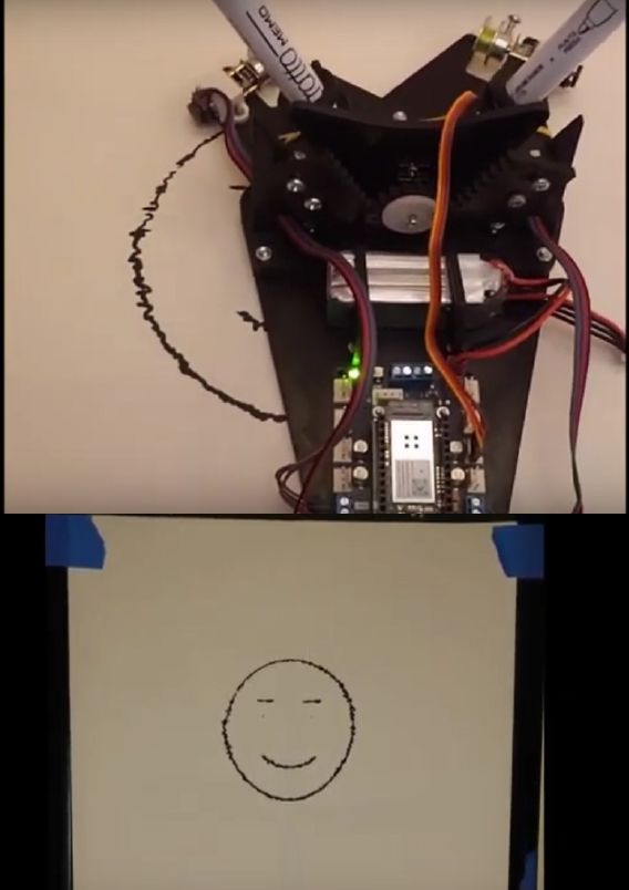
Following instructions in the Arduino Engineering Kit, students assembled a drawing robot using components from the kit, including DC motors, pulleys, servos, and a USB camera. The robot uses two DC motors attached to the pulleys to move itself across a whiteboard. Each motor includes an encoder that senses the rotational motion of the motor shaft. The robot draws on the whiteboard using markers attached to servo motors. When a servo is engaged, the marker is lowered to the drawing surface. While building the robot, students write MATLAB functions to test basic operations of the servos and the motor and pulley system.
In the final part of the project, students develop a program that can replicate an image placed in front of the robot’s camera. They write MATLAB code to capture an image from the camera, convert it to grayscale, and then convert it to a binary black-and-white image using Image Processing Toolbox™. They write a function to translate the pixel values in the processed image into 2D coordinate values and then into encoder counts, which are sent to the robot’s DC motors. Once the robot is in position, the program commands the servo to lower the marker as the robot moves to its next position (Figure 3).
Students spend several weeks working on the project, learning how to plan for conducting the project on a tight schedule, monitor progress using a Gantt chart, and handle real-world mechatronics challenges, including sensors with limited resolution. By working through these challenges and then presenting their robots to their classmates through video, the students gain confidence in their ability to communicate, troubleshoot, and find the resources they need.
Plans for a Return to In-Person Teaching
I will be using the Arduino Engineering Kit Rev2 for the next semester in an online synchronous setting. Although having the students work on their projects individually was feasible and helpful, when my in-person classes resume at SFSU, I plan to return to a team-based approach for at least some of the course assignments. Working together will enable the students to complete Arduino Engineering Kit projects more quickly, which means they might be able to build not only the drawing robot but also a self-balancing motorcycle and a mobile rover.
Published 2021

