dsp.FilterCascade
Create cascade of filter System objects
Description
The dsp.FilterCascade object creates a multistage
System object™ that enables cascading of filter System objects and scalar gains. This object
operates similar to the cascade function. However, the
cascade function does not support delay as a filter stage.
You can pass the dsp.FilterCascade
System object as a stage to another dsp.FilterCascade
System object. You can also pass dsp.FilterCascade
System object as an input to the cascade function.
When you call the object, the size, data type, and complexity of the input signal must be supported by all of the stages in the filter cascade. This object supports variable-size signals if the filter stages within the object support variable-size signals.
To filter a signal with a cascade of filters:
Create the
dsp.FilterCascadeobject and set its properties.Call the object with arguments, as if it were a function.
To learn more about how System objects work, see What Are System Objects?
Alternatively, you can generate a MATLAB® function from the filter cascade object, and call that function to filter a
signal. The generated function supports C/C++ code generation. For more details, see the
generateFilteringCode function.
Creation
Syntax
Description
FC = dsp.FilterCascadeFC that has a single stage, a dsp.FIRFilter
System object with default properties.
FC = dsp.FilterCascade(filt1,filt2,...,filtn)FC, with the first stage set to
filt1, the second stage set to filt2, and so on.
Each stage can be a filter System object or a scalar gain value.
For example, create a filter cascade that includes a lowpass filter, a highpass filter, and a gain stage.
lpFilt = dsp.LowpassFilter(StopbandFrequency=15000,...
                           PassbandFrequency=12000);
hpFilt = dsp.HighpassFilter(StopbandFrequency=5000,...
                            PassbandFrequency=8000);
gain = 2;
bpFilt = dsp.FilterCascade(lpFilt,hpFilt,2);
FC = dsp.FilterCascade(___,InputSampleRate=Value)
Positive real scalar — The input sample rate of the filter cascade is a positive real scalar.
"normalized"— The input sample rate of the filter cascade is in normalized frequency units regardless of the input sample rate of the individual filter stages."auto"— The input sample rate of the filter cascade is determined from the input sample rate of the individual filter stages as per these conditions:If all the filter stages have a normalized frequency, then the filter cascade has a normalized frequency.
If at least one filter stage has an absolute sample rate, then the filter cascade uses an absolute sample rate. The object determines this rate based on the rate conversion ratio of the stages within. For an example, see Specify Input Sample Rate in dsp.FilterCascade Object.
(since R2026a)
Properties
Usage
Syntax
Description
y = FC(x)x by using the filter cascade defined in
FC and returns filtered output y. The size,
data type, and complexity of the input signal must be supported by all of the stages in
the filter cascade. This object supports variable-size signals if the filter stages within
the object support variable-size signals.
Input Arguments
Output Arguments
Object Functions
To use an object function, specify the
System object as the first input argument. For
example, to release system resources of a System object named obj, use
this syntax:
release(obj)
Examples
Design a bandpass filter by cascading:
A highpass filter with a stopband frequency of 5000 Hz and a passband frequency of 8000 Hz
A lowpass filter with a passband frequency of 12,000 Hz and a stopband frequency of 15,000 Hz
Visualize the frequency response.
lpFilt = dsp.LowpassFilter(StopbandFrequency=15000,...
    PassbandFrequency=12000);
hpFilt = dsp.HighpassFilter(StopbandFrequency=5000,...
    PassbandFrequency=8000);

bpFilt = dsp.FilterCascade(lpFilt,hpFilt);

filterAnalyzer(bpFilt,FilterNames="BandpassFilter");

Pass a noisy sine wave as the input to the bandpass filter. The input is a sum of three sine waves with frequencies at 3 kHz, 10 kHz, and 15 kHz. The sampling frequency is 48 kHz. View the input and the filtered output on a spectrum analyzer.
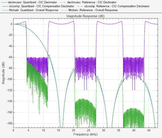
The tones at 3 kHz and 15 kHz are attenuated, and the tone at 10 kHz is preserved by the bandpass filter.
Sine1 = dsp.SineWave(Frequency=3e3,...
    SampleRate=48e3,...
    SamplesPerFrame=6000);
Sine2 = dsp.SineWave(Frequency=10e3,...
    SampleRate=48e3,...
    SamplesPerFrame=6000);
Sine3 = dsp.SineWave(Frequency=15e3,...
    SampleRate=48e3,...
    SamplesPerFrame=6000);

SpecAna = spectrumAnalyzer(...
    PlotAsTwoSidedSpectrum=false,...
    SampleRate=Sine1.SampleRate, ...
    ShowLegend=true, ...
    YLimits=[-160,60]);

SpecAna.ChannelNames = {"Original noisy signal","Filtered signal"};

for i = 1:1000
    x = Sine1()+Sine2()+Sine3()+0.1.*randn(Sine1.SamplesPerFrame,1);
    y = bpFilt(x);
    SpecAna(x,y);

end
release(SpecAna)

Create a CIC decimator. Cascade the decimator with a gain.
cicdecim = dsp.CICDecimator(...
    DecimationFactor=6,...
    NumSections=6);
decimcasc = dsp.FilterCascade(cicdecim,...
    1/gain(cicdecim));
Design a compensation decimator and cascade it with the filter cascade, decimcasc. This operation nests a dsp.FilterCascade object as a stage in another filter cascade. The CIC compensation decimator has an inherent gain, gain(cicdecim). The factor of 1/gain(cicdecim) from the decimation filter cascade, decimcasc, compensates for the compensation filter gain.
% Sample rate of input of compensation decimator
fs = 16e3;
% Passband frequency
fPass = 4e3;
% Stopband frequency
fStop = 4.5e3;
ciccomp = dsp.CICCompensationDecimator(cicdecim,...
    DecimationFactor=2, ...
    PassbandFrequency=fPass, ...
    StopbandFrequency=fStop, ...
    SampleRate=fs);
filtchain = dsp.FilterCascade(decimcasc,ciccomp);
Visualize the frequency response of the cascade of cascades.
f = filterAnalyzer(decimcasc,ciccomp,...
    filtchain,SampleRates=[fs*6,fs,fs*6],...
    Arithmetic="fixed");
setLegendStrings(f,["CIC Decimator",...
    "CIC Compensation Decimator",...
    "Overall Response"]);
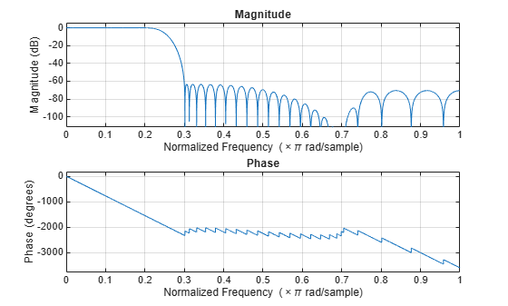
Design a two-stage decimator with a 100-Hz transition width, a 2-kHz sampling frequency, and 60-dB attenuation in the stopband. The decimator needs to downsample by a factor of 4.
filtCasc = designRateConverter(DecimationFactor=4,...
    InputSampleRate=2000,Bandwidth=200,StopbandAttenuation=60,...
    Verbose=true)
designRateConverter(InterpolationFactor=1, DecimationFactor=4, InputSampleRate=2000, Bandwidth=200, StopbandAttenuation=60, MaxStages=Inf, CostMethod="estimate", OptimizeFor="MPIS", Tolerance=0, ToleranceUnits="absolute")

Conversion ratio: 1:4
Input sample rate: 2000
Output sample rate: 500
filtCasc =
  dsp.FilterCascade with properties:

         Stage1: [1×1 dsp.FIRDecimator]
         Stage2: [1×1 dsp.FIRDecimator]
    CloneStages: true
Verify your design.
info(filtCasc)
ans =
    'Discrete-Time Filter Cascade
     ----------------------------
     Number of stages: 2
     Stage cloning: enabled
     Input sample rate: 2000
     ----------------------------

     Stage1: dsp.FIRDecimator
     -------
     Discrete-Time FIR Multirate Filter (real)
     -----------------------------------------
     Filter Structure   : Direct-Form FIR Polyphase Decimator
     Decimation Factor  : 2
     Polyphase Length   : 10
     Filter Length      : 19
     Stable             : Yes
     Linear Phase       : Yes (Type 1)

     Arithmetic         : double
     Input sample rate : 1


     Stage2: dsp.FIRDecimator
     -------
     Discrete-Time FIR Multirate Filter (real)
     -----------------------------------------
     Filter Structure   : Direct-Form FIR Polyphase Decimator
     Decimation Factor  : 2
     Polyphase Length   : 18
     Filter Length      : 35
     Stable             : Yes
     Linear Phase       : Yes (Type 1)

     Arithmetic         : double
     Input sample rate : 0.5

     '
freqz(filtCasc)
Generate code to filter data using this design. You cannot generate C/C++ code from the dsp.FilterCascade object directly, but you can generate C/C++ code from the generated function. The function defines the filter stages and calls them in sequence. The function is saved in a file called myDecimator.m in the current directory.
generateFilteringCode(filtCasc,"myDecimator");The myDecimator function creates a filter cascade and calls each stage object in turn.
type myDecimatorfunction y = myDecimator(x)
%MYDECIMATOR Construct a filter cascade and process its stages
% MATLAB Code
% Generated by MATLAB(R) 26.1 and DSP System Toolbox 26.1.
% Generated on: 19-Apr-2026 18:55:11
% To generate C/C++ code from this function use the codegen command.
% Type 'help codegen' for more information.
%#codegen
%% Construction
persistent firdn1 firdn2
if isempty(firdn1)
firdn1 = dsp.FIRDecimator( ...
Numerator=[0.0021878514650437845 0 -0.010189095418136306 0 0.031140395225498115 0 -0.082785931644222821 0 0.30979571849010851 0.5 0.30979571849010851 0 -0.082785931644222821 0 0.031140395225498115 0 -0.010189095418136306 0 0.0021878514650437845]);
firdn2 = dsp.FIRDecimator( ...
Numerator=[0.0011555011750488237 0 -0.0027482166351233102 0 0.0057681982289523072 0 -0.010736374060960912 0 0.018592020073668478 0 -0.031093723586671229 0 0.052603914610235683 0 -0.099130756073130377 0 0.31592697826202448 0.5 0.31592697826202448 0 -0.099130756073130377 0 0.052603914610235683 0 -0.031093723586671229 0 0.018592020073668478 0 -0.010736374060960912 0 0.0057681982289523072 0 -0.0027482166351233102 0 0.0011555011750488237]);
end
%% Process
y1 = firdn1(x);
y = firdn2(y1);
Since R2026a
Specify the input sample rate explicitly while constructing the dsp.FilterCascade object using the InputSampleRate argument.
Cascade with Absolute Sample Rate
Create a dsp.FilterCascade object with three stages. Each stage is a dsp.FIRFilter object operating in normalized frequency units. Specify the sample rate of the cascade as 22050 Hz using the InputSampleRate argument.
filtNorm1 = dsp.FIRFilter;
firtNorm2 = dsp.FIRFilter(designLowpassFIR(FilterOrder=30,CutoffFrequency=0.5,Window="hann"));
filtNorm3 = designLowpassFIR(FilterOrder=10,CutoffFrequency=0.5,SystemObject=true);
cascadeSpecifySampleRate = cascade(filtNorm1,firtNorm2,filtNorm3,InputSampleRate=22050)
cascadeSpecifySampleRate =
dsp.FilterCascade with properties:
Stage1: [1×1 dsp.FIRFilter]
Stage2: [1×1 dsp.FIRFilter]
Stage3: [1×1 dsp.FIRFilter]
CloneStages: true
The cascade operates at the absolute frequency that you specify regardless of the sample rate of the filter stages.
info(cascadeSpecifySampleRate)
ans =
    'Discrete-Time Filter Cascade
     ----------------------------
     Number of stages: 3
     Stage cloning: enabled
     Input sample rate: 22050
     ----------------------------

     Stage1: dsp.FIRFilter
     -------
     Discrete-Time FIR Filter (real)
     -------------------------------
     Filter Structure  : Direct-Form FIR
     Filter Length     : 2
     Stable            : Yes
     Linear Phase      : Yes (Type 2)
     Input sample rate : Normalized


     Stage2: dsp.FIRFilter
     -------
     Discrete-Time FIR Filter (real)
     -------------------------------
     Filter Structure  : Direct-Form FIR
     Filter Length     : 31
     Stable            : Yes
     Linear Phase      : Yes (Type 1)
     Input sample rate : Normalized


     Stage3: dsp.FIRFilter
     -------
     Discrete-Time FIR Filter (real)
     -------------------------------
     Filter Structure  : Direct-Form FIR
     Filter Length     : 11
     Stable            : Yes
     Linear Phase      : Yes (Type 1)
     Input sample rate : Normalized

     '
Cascade with Normalized Sample Rate
Specify normalized sample rate on the cascade. The first stage of the filter cascade has a sample rate of 17 Hz. The remaining filter stages operate in normalized frequency units.
filtAbs1 = dsp.FIRFilter(SampleRate=17);
firtNorm2 = dsp.FIRFilter(designLowpassFIR(FilterOrder=30,CutoffFrequency=0.5,Window="hann"));
filtNorm3 = designLowpassFIR(FilterOrder=10,CutoffFrequency=0.5,SystemObject=true);
cascadeNormSampleRate = cascade(filtAbs1,firtNorm2,filtNorm3,InputSampleRate="normalized")
cascadeNormSampleRate =
  dsp.FilterCascade with properties:

         Stage1: [1×1 dsp.FIRFilter]
         Stage2: [1×1 dsp.FIRFilter]
         Stage3: [1×1 dsp.FIRFilter]
    CloneStages: true
The cascade operates in normalized frequency units regardless of the sample rate of the individual filter stages.
info(cascadeNormSampleRate)
ans =
    'Discrete-Time Filter Cascade
     ----------------------------
     Number of stages: 3
     Stage cloning: enabled
     Input sample rate: Normalized
     ----------------------------

     Stage1: dsp.FIRFilter
     -------
     Discrete-Time FIR Filter (real)
     -------------------------------
     Filter Structure  : Direct-Form FIR
     Filter Length     : 2
     Stable            : Yes
     Linear Phase      : Yes (Type 2)
     Input sample rate : 17


     Stage2: dsp.FIRFilter
     -------
     Discrete-Time FIR Filter (real)
     -------------------------------
     Filter Structure  : Direct-Form FIR
     Filter Length     : 31
     Stable            : Yes
     Linear Phase      : Yes (Type 1)
     Input sample rate : Normalized


     Stage3: dsp.FIRFilter
     -------
     Discrete-Time FIR Filter (real)
     -------------------------------
     Filter Structure  : Direct-Form FIR
     Filter Length     : 11
     Stable            : Yes
     Linear Phase      : Yes (Type 1)
     Input sample rate : Normalized

     '
Cascade with Auto Sample Rate
Set the input sample rate of the cascade to "auto". The individual filter stages have a combination of normalized and absolute sample rates. The cascade uses the absolute sample rate.
filtAbs1 = dsp.FIRFilter(SampleRate=17);
firtNorm2 = dsp.FIRFilter(designLowpassFIR(FilterOrder=30,CutoffFrequency=0.5,Window="hann"));
filtAbs2 = dsp.FIRFilter(designLowpassFIR(FilterOrder=10,CutoffFrequency=0.5),SampleRate=17);
cascadeAutoSampleRate = cascade(filtAbs1,firtNorm2,filtAbs2,InputSampleRate="auto");
info(cascadeAutoSampleRate)
ans =
    'Discrete-Time Filter Cascade
     ----------------------------
     Number of stages: 3
     Stage cloning: enabled
     Input sample rate: 17
     ----------------------------

     Stage1: dsp.FIRFilter
     -------
     Discrete-Time FIR Filter (real)
     -------------------------------
     Filter Structure  : Direct-Form FIR
     Filter Length     : 2
     Stable            : Yes
     Linear Phase      : Yes (Type 2)
     Input sample rate : 17


     Stage2: dsp.FIRFilter
     -------
     Discrete-Time FIR Filter (real)
     -------------------------------
     Filter Structure  : Direct-Form FIR
     Filter Length     : 31
     Stable            : Yes
     Linear Phase      : Yes (Type 1)
     Input sample rate : Normalized


     Stage3: dsp.FIRFilter
     -------
     Discrete-Time FIR Filter (real)
     -------------------------------
     Filter Structure  : Direct-Form FIR
     Filter Length     : 11
     Stable            : Yes
     Linear Phase      : Yes (Type 1)
     Input sample rate : 17

     '
The input sample rate of the cascade is set to "auto". If there is a conversion ratio in the individual filter stages, the input sample rate of the cascade takes the conversion ratio into account. The second stage drops the sample rate by 3 and the third stage paces the cascade at 17 Hz. Therefore, the input sample rate of the cascade is 317 = 51 Hz.
filtNorm1 = dsp.FIRFilter; % Normalized frequency
filtNorm4 = dsp.FIRDecimator(3);  % Normalized frequency
filtAbs3 = dsp.SOSFilter(SampleRate=17); % Absolute frequency
cascadeAutoSampleRate2 = cascade(filtNorm1,filtNorm4,filtAbs3,InputSampleRate="auto");
info(cascadeAutoSampleRate2)
ans =
    'Discrete-Time Filter Cascade
     ----------------------------
     Number of stages: 3
     Stage cloning: enabled
     Input sample rate: 51
     ----------------------------

     Stage1: dsp.FIRFilter
     -------
     Discrete-Time FIR Filter (real)
     -------------------------------
     Filter Structure  : Direct-Form FIR
     Filter Length     : 2
     Stable            : Yes
     Linear Phase      : Yes (Type 2)
     Input sample rate : Normalized


     Stage2: dsp.FIRDecimator
     -------
     Discrete-Time FIR Multirate Filter (real)
     -----------------------------------------
     Filter Structure   : Direct-Form FIR Polyphase Decimator
     Decimation Factor  : 3
     Polyphase Length   : 24
     Filter Length      : 72
     Stable             : Yes
     Linear Phase       : Yes (Type 1)

     Arithmetic         : double
     Input sample rate : Normalized


     Stage3: dsp.SOSFilter
     -------
     Discrete-Time IIR Filter (real)
     -------------------------------
     Filter Structure    : Direct-Form II Transposed, Second-Order Sections
     Number of Sections  : 1
     Stable              : Yes
     Linear Phase        : No
     Input sample rate : 17

     '
Consider a cascade with nested cascades. The input sample rate of the first cascade is 22050 Hz. The input sample rate of the second cascade is "normalized". Cascade these two filter structures and set the input sample rate of the overall filter cascade to "auto".
filtCascadeSpecifySampleRate = dsp.FilterCascade(InputSampleRate=22050)
filtCascadeSpecifySampleRate =
  dsp.FilterCascade with properties:

         Stage1: [1×1 dsp.FIRFilter]
    CloneStages: true
filtCascadeNormSampleRate = dsp.FilterCascade(InputSampleRate="normalized")filtCascadeNormSampleRate =
dsp.FilterCascade with properties:
Stage1: [1×1 dsp.FIRFilter]
CloneStages: true
filtNestedCasacade = cascade(filtCascadeSpecifySampleRate,filtCascadeNormSampleRate,InputSampleRate="auto")filtNestedCasacade =
dsp.FilterCascade with properties:
Stage1: [1×1 dsp.FilterCascade]
Stage2: [1×1 dsp.FilterCascade]
CloneStages: true
The first filter cascade has an absolute sample rate and the second filter cascade operates in normalized frequency units. The nested filter cascade in the "auto" configuration uses the absolute sample rate.
info(filtNestedCasacade)
ans =
    'Discrete-Time Filter Cascade
     ----------------------------
     Number of stages: 2
     Stage cloning: enabled
     Input sample rate: Normalized
     ----------------------------

     Stage1: dsp.FilterCascade
     -------
     Discrete-Time Filter Cascade
     ----------------------------
     Number of stages: 1
     Stage cloning: enabled
     Input sample rate: 22050
     ----------------------------

     Stage1: dsp.FIRFilter
     -------
     Discrete-Time FIR Filter (real)
     -------------------------------
     Filter Structure  : Direct-Form FIR
     Filter Length     : 2
     Stable            : Yes
     Linear Phase      : Yes (Type 2)
     Input sample rate : Normalized


     Stage2: dsp.FilterCascade
     -------
     Discrete-Time Filter Cascade
     ----------------------------
     Number of stages: 1
     Stage cloning: enabled
     Input sample rate: Normalized
     ----------------------------

     Stage1: dsp.FIRFilter
     -------
     Discrete-Time FIR Filter (real)
     -------------------------------
     Filter Structure  : Direct-Form FIR
     Filter Length     : 2
     Stable            : Yes
     Linear Phase      : Yes (Type 2)
     Input sample rate : Normalized


     '
Since R2026a
Create a dsp.FilterCascade object with these filter stages:
dsp.FIRFilterobjectdsp.SOSFilterobjectdsp.FourthOrderSectionFilterobjectdsp.IIRFilterobjectA scalar value of 3
Create a dsp.FIRFilter object using the designLowpassFIR function.
firFilt = designLowpassFIR(FilterOrder=8,SystemObject=true);
Create a dsp.SOSFilter object using the designLowpassIIR function.
sosFilt = designLowpassIIR(FilterOrder=8,HasScaleValues=true,...
    SystemObject=true);
Create a dsp.FourthOrderSectionFilter object. Specify the filter coefficients.
fosNum =[0.0135    0.0541    0.0812    0.0541    0.0135
         0.0080    0.0319    0.0478    0.0319    0.0080];
fosDen =[1.0000   -2.2581    2.4552   -1.3108    0.3302
         1.0000   -1.7257    1.1842   -0.3779    0.0470];
fosFilt = dsp.FourthOrderSectionFilter(fosNum,fosDen);
Create a dsp.IIRFilter object. Specify the filter coefficients.
sosNum = [0.1287    0.2574    0.1287
          0.1051    0.2103    0.1051
          0.0922    0.1844    0.0922
          0.0865    0.1729    0.0865];
sosDen = [1.0000   -1.2428    0.7575
          1.0000   -1.0153    0.4359
          1.0000   -0.8906    0.2595
          1.0000   -0.8351    0.1810];
iirFilt = dsp.IIRFilter(sos2tf([sosNum,sosDen]));
Cascade these filters into a single dsp.FilterCascade object using the cascade function.
filtCascadeObj = cascade(firFilt,cascade(sosFilt,fosFilt),...
    3,iirFilt)
filtCascadeObj =
dsp.FilterCascade with properties:
Stage1: [1×1 dsp.FIRFilter]
Stage2: [1×1 dsp.FilterCascade]
Stage3: 3
Stage4: [1×1 dsp.IIRFilter]
CloneStages: true
Use the ctf function to obtain the filter coefficients and scale values of the overall filter cascade in the CTF format.
[cascNum,cascDen,cascSV] = ctf(filtCascadeObj)
cascNum = 9×9

    0.0000    0.0191    0.1019    0.2309    0.2963    0.2309    0.1019    0.0191    0.0000
    1.0000    2.0000    1.0000         0         0         0         0         0         0
    1.0000    2.0000    1.0000         0         0         0         0         0         0
    1.0000    2.0000    1.0000         0         0         0         0         0         0
    1.0000    2.0000    1.0000         0         0         0         0         0         0
    0.0135    0.0541    0.0812    0.0541    0.0135         0         0         0         0
    0.0080    0.0319    0.0478    0.0319    0.0080         0         0         0         0
    3.0000         0         0         0         0         0         0         0         0
    0.0001    0.0009    0.0030    0.0060    0.0076    0.0060    0.0030    0.0009    0.0001
cascDen = 9×5

    1.0000         0         0         0         0
    1.0000   -1.2428    0.7575         0         0
    1.0000   -1.0153    0.4359         0         0
    1.0000   -0.8906    0.2595         0         0
    1.0000   -0.8351    0.1810         0         0
    1.0000   -2.2581    2.4552   -1.3108    0.3302
    1.0000   -1.7257    1.1842   -0.3779    0.0470
    1.0000         0         0         0         0
    1.0000    0.1000         0         0         0
cascSV = 10×1

    1.0000
    0.1287
    0.1051
    0.0922
    0.0865
    1.0000
    1.0000
    1.0000
    1.0000
    1.0000