Field-Oriented Control of PMSM with Encoder Using Infineon AURIX Microcontrollers
R2026bThis example shows you how to implement the field-oriented control (FOC) technique to control the speed of a permanent magnet synchronous motor (PMSM). The FOC algorithm requires rotor position feedback, which is obtained by using an encoder sensor. For more details about FOC, see Field-Oriented Control (Motor Control Blockset).
A closed-loop FOC algorithm is used to regulate the speed and torque of a PMSM. You can use this example to implement position control applications by using closed-loop FOC. The example drives the motor to reach the speed value. This example uses AURIX™ peripheral blocks from the Embedded Coder® Support Package for Infineon® AURIX TC4x Microcontrollers and MCB library blocks from Motor Control Blockset.
Prerequisites
For more information on hardware setup and required third-party toolchains to compile the generated code, see Hardware Setup for Infineon AURIX Microcontrollers and For more information on hardware setup and required third-party toolchains to compile the generated code, see Hardware Setup for Infineon AURIX Microcontrollers and Supported Hardware and Required Software.
For more information on deploying a Simulink model to a hardware board, see Getting Started with Embedded Coder Support Package for Infineon AURIX TC4x Microcontrollers.
Required Hardware
Infineon AURIX TC4x hardware board
AURIX Motor Control Power Board
Nanotec DB42S02 Electric motor
WEDL5541-B14-KIT (5 mm) Incremental Encoder
Hardware Connection
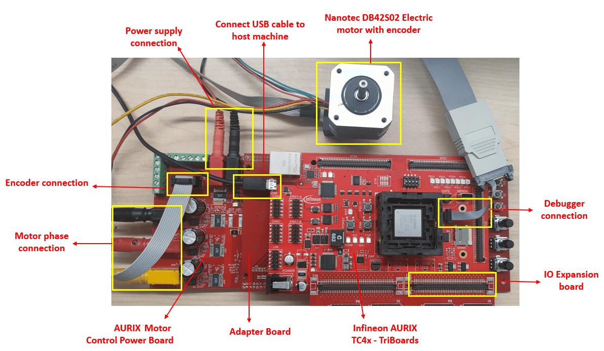
Connect the required hardware as shown in this diagram.
Available Model
The example includes the tc4x_mcb_pmsm_foc_encoder model.
You can use this model for both simulation and code generation.
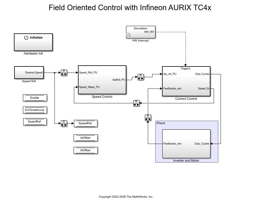
You can change the model parameters to fit your specific motor. The controller algorithm generates space vector PWM signals to drive the inverter switches. The inverter measures the current of the two motor inputs (ia and ib) input currents to the motor (ia and ib) using two analog-to-digital converters (ADCs) and sends the measurements to the processor.
This example uses the encoder sensor to measure the rotor position. The encoder sensor consists of a disk with two tracks or channels that are coded 90 electrical degrees out of phase. This creates two pulses (A and B) that have a phase difference of 90 degrees and an index pulse (I). The controller uses the phase relationship between A and B channels and the transition of channel states to determine the direction of rotation of the motor.
Configure the Model
1. Open the tc4x_mcb_pmsm_foc_encoder model.
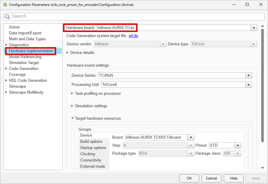
2. Press Ctrl+E to open the Configuration Parameters dialog box. Click Hardware Implementation in the left pane. Set Hardware board to Infineon AURIX TC4x. Under Hardware board settings, expand Target hardware resources. Set the Series and Package class parameters to match your hardware.
3. The example includes the tc4x_mcb_pmsm_foc_encoder_data script, which defines the motor, inverter, and control parameters required for FOC of a PMSM. To configure the model for a different motor, modify the motor parameters in this script.
4. The model is pre-configured for the Infineon AURIX TC4xx TriBoard. If you use the Infineon AURIX TC497N Control Board, in the Hardware Mapping tool, update the pin assignments and ADC channel mappings to match your hardware connections. For more information, see Deploy Motor Control Applications to TC497N Control Board.
Peripheral Block Configurations
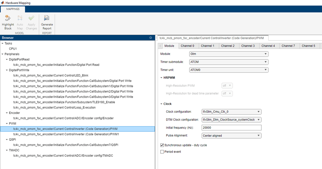
Set the peripheral block configurations for this model using the Hardware Mapping tool.
1. In the Simulink toolstrip, go to Hardware tab and click Hardware Mapping.

2. The following figure shows the PWM peripheral block configuration in Hardware Mapping tool. Similarly the model is configured for other peripherals. A preconfigured model is included for your convenience.
Simulate Model
Complete the following steps to simulate the model.
1. Open tc4x_mcb_pmsm_foc_encoder model.
2. Click Run on the Simulation tab to simulate the model.
3. Click Data Inspector on the Simulation tab to view and analyze the simulation results.
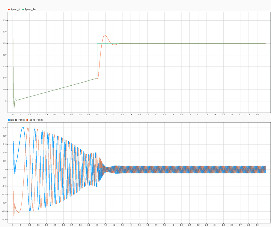
4. During simulation, run the model in open loop for 1 second and switch to closed loop with 0.25 and 0.9 speed per unit for 20 sec. Observe the measured currents per unit and speed feedback following the reference set point.
Generate Code and Deploy Model to Target Hardware
Complete the following steps to generate code and run the FOC algorithm on the target hardware.
1. Open tc4x_mcb_pmsm_foc_encoder model
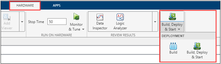
2. Click Build, Deploy & Start on the Hardware tab to deploy the target model to the hardware.
3. Follow the build process by opening the diagnostic viewer using the link provided at the bottom of the model canvas. You can observe the code generation report that contains code for model traceability. Infineon AURIX deploys the model to the hardware using a downloading tool.
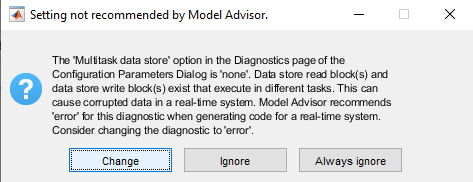
Note: You can ignore the model advisor warning message while trying to build the model.
4. Download and install the One Eye tool from Infineon to monitor signals from the hardware. Before using the One Eye tool, ensure that you download and install the latest version of the TAS/DAS tool.
5. Open the One Eye tool. Load tc4x_mcb_pmsm_foc_encoder.OneEye file shipped with this example by clicking File > Load Configuration in the One Eye tool.
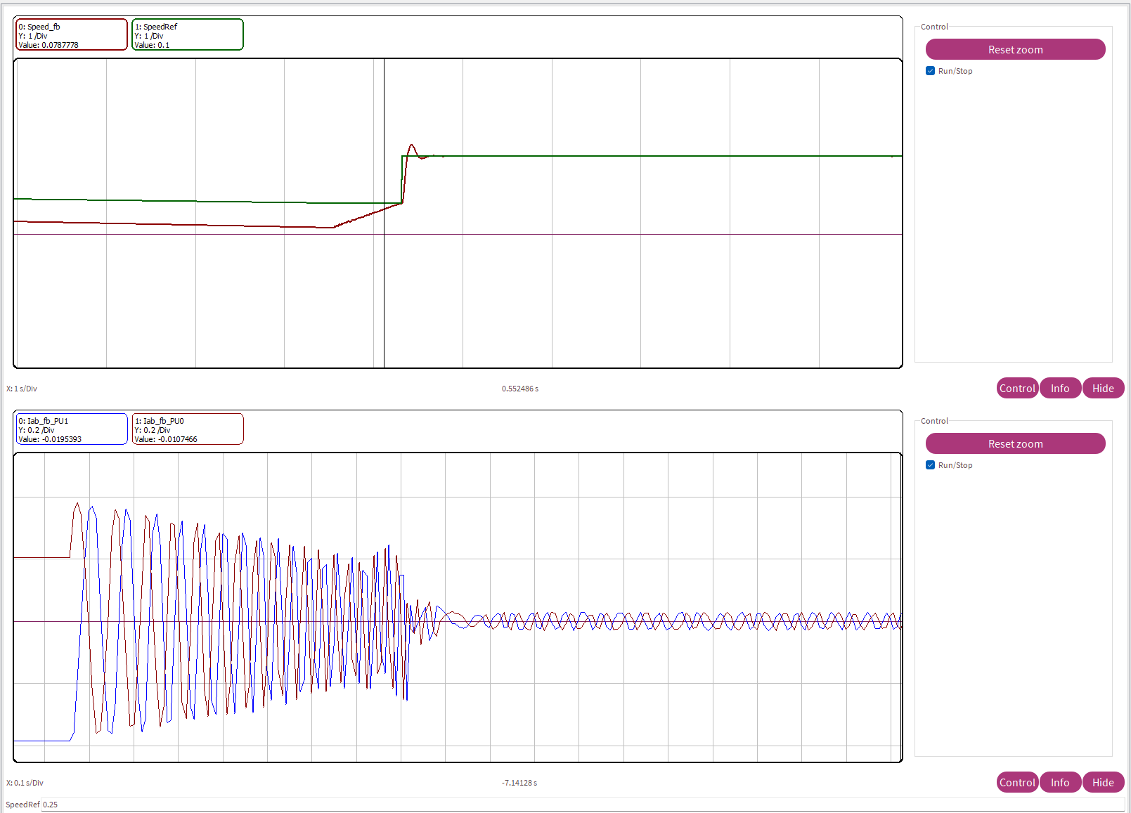
6. Load the tc4x_mcb_pmsm_foc_encoder.elf file generated in Step 3 and observe the measured currents (Iab_fb_PU1, Iab_fb_PU0), speed feedback (Speed_fb) following the reference set point (SpeedRef).
Other Things to Try
The model is pre-configured for the Infineon AURIX TC4xx TriBoard. If you use an Infineon AURIX TC4xx Control Board, in the Hardware Mapping tool, update the pin assignments and ADC channel mappings to match your hardware connections. For more information, see Deploy Motor Control Applications to TC497N Control Board.
Compare encoder-based FOC performance with the EEMF observer performance from the Field-Oriented Control of PMSM with Encoder Using Infineon AURIX Microcontrollers.

