imuSensor
IMU simulation model
Description
The imuSensor
System object™ models receiving data from an inertial measurement unit (IMU). The object
generates sensor readings in the sensor body coordinate system based on inputs specified in a
local navigation coordinate system. For more information on how output readings are
calculated, see the Algorithms section.
You can specify the reference frame of the block inputs as one of the local navigation
coordinate systems, the NED (North-East-Down) or ENU
(East-North-Up), by using the RF
To model an IMU:
Create the
imuSensorobject and set its properties.Call the object with arguments, as if it were a function.
To learn more about how System objects work, see What Are System Objects?
Creation
Syntax
Description
IMU = imuSensorIMU, that computes an inertial measurement unit reading
based on an inertial input signal. IMU has an ideal accelerometer and
gyroscope.
IMU = imuSensor( returns an
'accel-gyro')imuSensor
System object with an ideal accelerometer and gyroscope. imuSensor and
imuSensor('accel-gyro') are equivalent creation syntaxes.
IMU = imuSensor( returns an
'accel-mag')imuSensor
System object with an ideal accelerometer and magnetometer.
IMU = imuSensor( returns an
'accel-gyro-mag')imuSensor
System object with an ideal accelerometer, gyroscope, and magnetometer.
IMU = imuSensor(___,"ReferenceFrame",
returns an RF)imuSensor
System object that computes an inertial measurement unit reading relative to the reference
frame RF.
IMU = imuSensor(___,
sets one or more properties using name-value arguments in addition to any of the previous
input arguments.Name=Value)
Input Arguments
Properties
Usage
Syntax
Description
[
generates accelerometer and gyroscope readings from the acceleration and angular
velocity inputs.accelReadings,gyroReadings] = IMU(acc,angVel)
This syntax is only valid if IMUType is set to
'accel-gyro' or 'accel-gyro-mag'.
[
generates accelerometer and gyroscope readings from the acceleration, angular velocity,
and orientation inputs.accelReadings,gyroReadings] = IMU(acc,angVel,orientation)
This syntax is only valid if IMUType is set to
'accel-gyro' or 'accel-gyro-mag'.
[
generates accelerometer and magnetometer readings from the acceleration and angular
velocity inputs.accelReadings,magReadings] = IMU(acc,angVel)
This syntax is only valid if IMUType is set to
'accel-mag'.
[
generates accelerometer and magnetometer readings from the acceleration, angular
velocity, and orientation inputs.accelReadings,magReadings] = IMU(acc,angVel,orientation)
This syntax is only valid if IMUType is set to
'accel-mag'.
[
generates accelerometer, gyroscope, and magnetometer readings from the acceleration and
angular velocity inputs.accelReadings,gyroReadings,magReadings] = IMU(acc,angVel)
This syntax is only valid if IMUType is set to
'accel-gyro-mag'.
[
generates accelerometer, gyroscope, and magnetometer readings from the acceleration,
angular velocity, and orientation inputs.accelReadings,gyroReadings,magReadings] = IMU(acc,angVel,orientation)
This syntax is only valid if IMUType is set to
'accel-gyro-mag'.
Input Arguments
Output Arguments
Object Functions
To use an object function, specify the
System object as the first input argument. For
example, to release system resources of a System object named obj, use
this syntax:
release(obj)
Examples
The imuSensor System object™ enables you to model the data received from an inertial measurement unit consisting of a combination of gyroscope, accelerometer, and magnetometer.
Create a default imuSensor object.
IMU = imuSensor
IMU =
  imuSensor with properties:

          IMUType: 'accel-gyro'
       SampleRate: 100
      Temperature: 25
    Accelerometer: [1×1 accelparams]
        Gyroscope: [1×1 gyroparams]
     RandomStream: 'Global stream'
The imuSensor object, IMU, contains an idealized gyroscope and accelerometer. Use dot notation to view properties of the gyroscope.
IMU.Gyroscope
ans =
  gyroparams with properties:

    MeasurementRange: Inf             rad/s
          Resolution: 0               (rad/s)/LSB
        ConstantBias: [0 0 0]         rad/s
    AxesMisalignment: [3⨯3 double]    %

                   NoiseDensity: [0 0 0]           (rad/s)/√Hz
                BiasInstability: [0 0 0]           rad/s
                     RandomWalk: [0 0 0]           (rad/s)*√Hz
                      NoiseType: "double-sided"
    BiasInstabilityCoefficients: [1⨯1 struct]

           TemperatureBias: [0 0 0]    (rad/s)/°C
    TemperatureScaleFactor: [0 0 0]    %/°C
          AccelerationBias: [0 0 0]    (rad/s)/(m/s²)
Sensor properties are defined by corresponding parameter objects. For example, the gyroscope model used by the imuSensor is defined by an instance of the gyroparams class. You can modify properties of the gyroscope model using dot notation. Set the gyroscope measurement range to 4.3 rad/s.
IMU.Gyroscope.MeasurementRange = 4.3;
You can also set sensor properties to preset parameter objects. Create an accelparams object to mimic specific hardware, and then set the IMU Accelerometer property to the accelparams object. Display the Accelerometer property to verify the properties are correctly set.
SpecSheet1 = accelparams( ...
    'MeasurementRange',19.62, ...
    'Resolution',0.00059875, ...
    'ConstantBias',0.4905, ...
    'AxesMisalignment',2, ...
    'NoiseDensity',0.003924, ...
    'BiasInstability',0, ...
    'TemperatureBias', [0.34335 0.34335 0.5886], ...
    'TemperatureScaleFactor', 0.02);

IMU.Accelerometer = SpecSheet1;

IMU.Accelerometer
ans =
  accelparams with properties:

    MeasurementRange: 19.62                     m/s²
          Resolution: 0.00059875                (m/s²)/LSB
        ConstantBias: [0.4905 0.4905 0.4905]    m/s²
    AxesMisalignment: [3⨯3 double]              %

                   NoiseDensity: [0.003924 0.003924 0.003924]    (m/s²)/√Hz
                BiasInstability: [0 0 0]                         m/s²
                     RandomWalk: [0 0 0]                         (m/s²)*√Hz
                      NoiseType: "double-sided"
    BiasInstabilityCoefficients: [1⨯1 struct]

           TemperatureBias: [0.34335 0.34335 0.5886]    (m/s²)/°C
    TemperatureScaleFactor: [0.02 0.02 0.02]            %/°C
Use the imuSensor System object™ to model receiving data from a stationary ideal IMU containing an accelerometer, gyroscope, and magnetometer.
Create an ideal IMU sensor model that contains an accelerometer, gyroscope, and magnetometer.
IMU = imuSensor('accel-gyro-mag')IMU =
imuSensor with properties:
IMUType: 'accel-gyro-mag'
SampleRate: 100
Temperature: 25
MagneticField: [27.5550 -2.4169 -16.0849]
Accelerometer: [1×1 accelparams]
Gyroscope: [1×1 gyroparams]
Magnetometer: [1×1 magparams]
RandomStream: 'Global stream'
Define the ground-truth, underlying motion of the IMU you are modeling. The acceleration and angular velocity are defined relative to the local NED coordinate system.
numSamples = 1000;
acceleration = zeros(numSamples,3);
angularVelocity = zeros(numSamples,3);
Call IMU with the ground-truth acceleration and angular velocity. The object outputs accelerometer readings, gyroscope readings, and magnetometer readings, as modeled by the properties of the imuSensor System object. The accelerometer readings, gyroscope readings, and magnetometer readings are relative to the IMU sensor body coordinate system.
[accelReading,gyroReading,magReading] = IMU(acceleration,angularVelocity);
Plot the accelerometer readings, gyroscope readings, and magnetometer readings.
t = (0:(numSamples-1))/IMU.SampleRate;
subplot(3,1,1)
plot(t,accelReading)
legend('X-axis','Y-axis','Z-axis')
title('Accelerometer Readings')
ylabel('Acceleration (m/s^2)')

subplot(3,1,2)
plot(t,gyroReading)
legend('X-axis','Y-axis','Z-axis')
title('Gyroscope Readings')
ylabel('Angular Velocity (rad/s)')

subplot(3,1,3)
plot(t,magReading)
legend('X-axis','Y-axis','Z-axis')
title('Magnetometer Readings')
xlabel('Time (s)')
ylabel('Magnetic Field (uT)')

Orientation is not specified and the ground-truth motion is stationary, so the IMU sensor body coordinate system and the local NED coordinate system overlap for the entire simulation.
Accelerometer readings: The z-axis of the sensor body corresponds to the Down-axis. The 9.8 m/s^2 acceleration along the z-axis is due to gravity.
Gyroscope readings: The gyroscope readings are zero along each axis, as expected.
Magnetometer readings: Because the sensor body coordinate system is aligned with the local NED coordinate system, the magnetometer readings correspond to the
MagneticFieldproperty ofimuSensor. TheMagneticFieldproperty is defined in the local NED coordinate system.
Use imuSensor to model data obtained from a rotating IMU containing an ideal accelerometer and an ideal magnetometer. Use kinematicTrajectory to define the ground-truth motion. Fuse the imuSensor model output using the ecompass function to determine orientation over time.
Define the ground-truth motion for a platform that rotates 360 degrees in four seconds, and then another 360 degrees in two seconds. Use kinematicTrajectory to output the orientation, acceleration, and angular velocity in the NED coordinate system.
fs = 100;
firstLoopNumSamples = fs*4;
secondLoopNumSamples = fs*2;
totalNumSamples = firstLoopNumSamples + secondLoopNumSamples;

traj = kinematicTrajectory('SampleRate',fs);

accBody = zeros(totalNumSamples,3);
angVelBody = zeros(totalNumSamples,3);
angVelBody(1:firstLoopNumSamples,3) = (2*pi)/4;
angVelBody(firstLoopNumSamples+1:end,3) = (2*pi)/2;

[~,orientationNED,~,accNED,angVelNED] = traj(accBody,angVelBody);
Create an imuSensor object with an ideal accelerometer and an ideal magnetometer. Call IMU with the ground-truth acceleration, angular velocity, and orientation to output accelerometer readings and magnetometer readings. Plot the results.
IMU = imuSensor('accel-mag','SampleRate',fs);

[accelReadings,magReadings] = IMU(accNED,angVelNED,orientationNED);

figure(1)
t = (0:(totalNumSamples-1))/fs;
subplot(2,1,1)
plot(t,accelReadings)
legend('X-axis','Y-axis','Z-axis')
ylabel('Acceleration (m/s^2)')
title('Accelerometer Readings')

subplot(2,1,2)
plot(t,magReadings)
legend('X-axis','Y-axis','Z-axis')
ylabel('Magnetic Field (\muT)')
xlabel('Time (s)')
title('Magnetometer Readings')
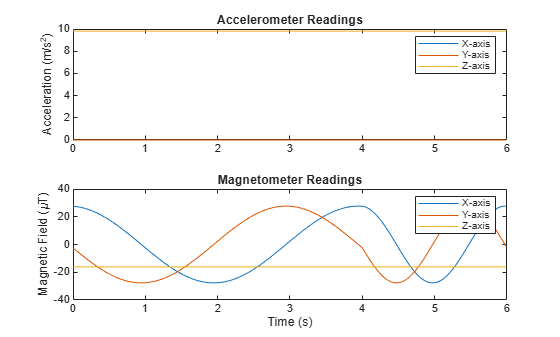
The accelerometer readings indicate that the platform has no translation. The magnetometer readings indicate that the platform is rotating around the z-axis.
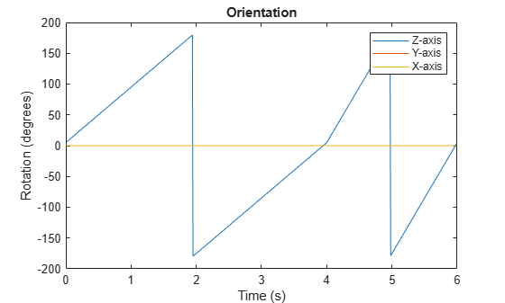
Feed the accelerometer and magnetometer readings into the ecompass function to estimate the orientation over time. The ecompass function returns orientation in quaternion format. Convert orientation to Euler angles and plot the results. The orientation plot indicates that the platform rotates about the z-axis only.
orientation = ecompass(accelReadings,magReadings);

orientationEuler = eulerd(orientation,'ZYX','frame');

figure(2)
plot(t,orientationEuler)
legend('Z-axis','Y-axis','X-axis')
xlabel('Time (s)')
ylabel('Rotation (degrees)')
title('Orientation')
Use imuSensor to model data obtained from a rotating IMU containing a realistic accelerometer and a realistic magnetometer. Use kinematicTrajectory to define the ground-truth motion. Fuse the imuSensor model output using the ecompass function to determine orientation over time.
Define the ground-truth motion for a platform that rotates 360 degrees in four seconds, and then another 360 degrees in two seconds. Use kinematicTrajectory to output the orientation, acceleration, and angular velocity in the NED coordinate system.
fs = 100;
firstLoopNumSamples = fs*4;
secondLoopNumSamples = fs*2;
totalNumSamples = firstLoopNumSamples + secondLoopNumSamples;

traj = kinematicTrajectory('SampleRate',fs);

accBody = zeros(totalNumSamples,3);
angVelBody = zeros(totalNumSamples,3);
angVelBody(1:firstLoopNumSamples,3) = (2*pi)/4;
angVelBody(firstLoopNumSamples+1:end,3) = (2*pi)/2;

[~,orientationNED,~,accNED,angVelNED] = traj(accBody,angVelBody);
Create an imuSensor object with a realistic accelerometer and a realistic magnetometer. Call IMU with the ground-truth acceleration, angular velocity, and orientation to output accelerometer readings and magnetometer readings. Plot the results.
IMU = imuSensor('accel-mag','SampleRate',fs);

IMU.Accelerometer = accelparams( ...
    'MeasurementRange',19.62, ...            % m/s^2
    'Resolution',0.0023936, ...              % m/s^2 / LSB
    'TemperatureScaleFactor',0.008, ...      % % / degree C
    'ConstantBias',0.1962, ...               % m/s^2
    'TemperatureBias',0.0014715, ...         % m/s^2 / degree C
    'NoiseDensity',0.0012361);               % m/s^2 / Hz^(1/2)

IMU.Magnetometer = magparams( ...
    'MeasurementRange',1200, ...             % uT
    'Resolution',0.1, ...                    % uT / LSB
    'TemperatureScaleFactor',0.1, ...        % % / degree C
    'ConstantBias',1, ...                    % uT
    'TemperatureBias',[0.8 0.8 2.4], ...     % uT / degree C
    'NoiseDensity',[0.6 0.6 0.9]/sqrt(100)); % uT / Hz^(1/2)

[accelReadings,magReadings] = IMU(accNED,angVelNED,orientationNED);

figure(1)
t = (0:(totalNumSamples-1))/fs;
subplot(2,1,1)
plot(t,accelReadings)
legend('X-axis','Y-axis','Z-axis')
ylabel('Acceleration (m/s^2)')
title('Accelerometer Readings')

subplot(2,1,2)
plot(t,magReadings)
legend('X-axis','Y-axis','Z-axis')
ylabel('Magnetic Field (\muT)')
xlabel('Time (s)')
title('Magnetometer Readings')
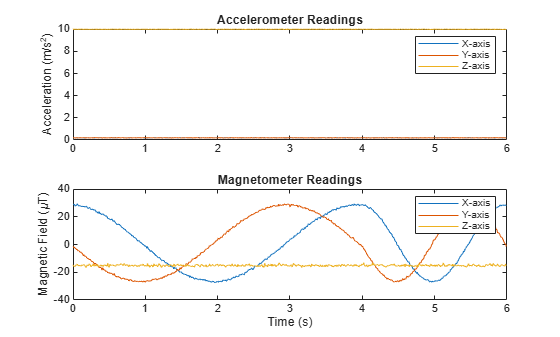
The accelerometer readings indicate that the platform has no translation. The magnetometer readings indicate that the platform is rotating around the z-axis.
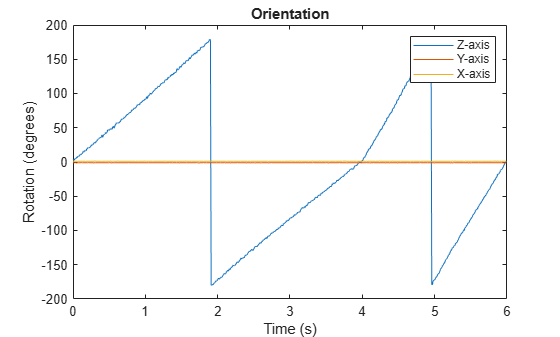
Feed the accelerometer and magnetometer readings into the ecompass function to estimate the orientation over time. The ecompass function returns orientation in quaternion format. Convert orientation to Euler angles and plot the results. The orientation plot indicates that the platform rotates about the z-axis only.
orientation = ecompass(accelReadings,magReadings);

orientationEuler = eulerd(orientation,'ZYX','frame');

figure(2)
plot(t,orientationEuler)
legend('Z-axis','Y-axis','X-axis')
xlabel('Time (s)')
ylabel('Rotation (degrees)')
title('Orientation')
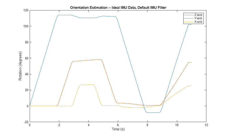
%Model a tilting IMU that contains an accelerometer and gyroscope using the imuSensor System object™. Use ideal and realistic models to compare the results of orientation tracking using the imufilter System object.
Load a struct describing ground-truth motion and a sample rate. The motion struct describes sequential rotations:
yaw: 120 degrees over two seconds
pitch: 60 degrees over one second
roll: 30 degrees over one-half second
roll: -30 degrees over one-half second
pitch: -60 degrees over one second
yaw: -120 degrees over two seconds
In the last stage, the motion struct combines the 1st, 2nd, and 3rd rotations into a single-axis rotation. The acceleration, angular velocity, and orientation are defined in the local NED coordinate system.
load y120p60r30.mat motion fs
accNED = motion.Acceleration;
angVelNED = motion.AngularVelocity;
orientationNED = motion.Orientation;

numSamples = size(motion.Orientation,1);
t = (0:(numSamples-1)).'/fs;
Create an ideal IMU sensor object and a default IMU filter object.
IMU = imuSensor('accel-gyro','SampleRate',fs);

aFilter = imufilter('SampleRate',fs);
In a loop:
Simulate IMU output by feeding the ground-truth motion to the IMU sensor object.
Filter the IMU output using the default IMU filter object.
orientation = zeros(numSamples,1,'quaternion');
for i = 1:numSamples

    [accelBody,gyroBody] = IMU(accNED(i,:),angVelNED(i,:),orientationNED(i,:));

    orientation(i) = aFilter(accelBody,gyroBody);

end
release(aFilter)
Plot the orientation over time.
figure(1)
plot(t,eulerd(orientation,'ZYX','frame'))
xlabel('Time (s)')
ylabel('Rotation (degrees)')
title('Orientation Estimation -- Ideal IMU Data, Default IMU Filter')
legend('Z-axis','Y-axis','X-axis')
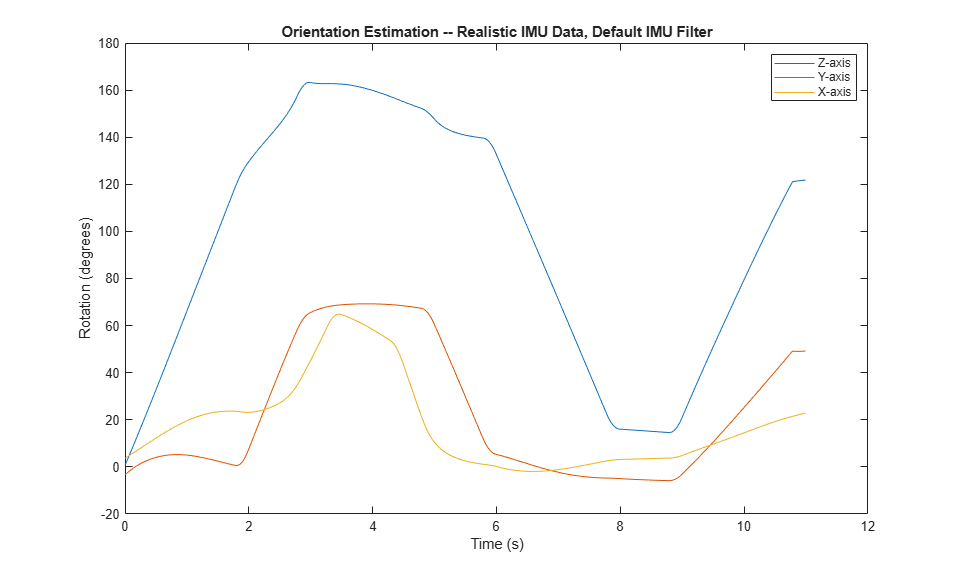
Modify properties of your imuSensor to model real-world sensors. Run the loop again and plot the orientation estimate over time.
IMU.Accelerometer = accelparams( ...
    'MeasurementRange',19.62, ...
    'Resolution',0.00059875, ...
    'ConstantBias',0.4905, ...
    'AxesMisalignment',2, ...
    'NoiseDensity',0.003924, ...
    'BiasInstability',0, ...
    'TemperatureBias', [0.34335 0.34335 0.5886], ...
    'TemperatureScaleFactor',0.02);
IMU.Gyroscope = gyroparams( ...
    'MeasurementRange',4.3633, ...
    'Resolution',0.00013323, ...
    'AxesMisalignment',2, ...
    'NoiseDensity',8.7266e-05, ...
    'TemperatureBias',0.34907, ...
    'TemperatureScaleFactor',0.02, ...
    'AccelerationBias',0.00017809, ...
    'ConstantBias',[0.3491,0.5,0]);

orientationDefault = zeros(numSamples,1,'quaternion');
for i = 1:numSamples

    [accelBody,gyroBody] = IMU(accNED(i,:),angVelNED(i,:),orientationNED(i,:));

    orientationDefault(i) = aFilter(accelBody,gyroBody);

end
release(aFilter)

figure(2)
plot(t,eulerd(orientationDefault,'ZYX','frame'))
xlabel('Time (s)')
ylabel('Rotation (degrees)')
title('Orientation Estimation -- Realistic IMU Data, Default IMU Filter')
legend('Z-axis','Y-axis','X-axis')
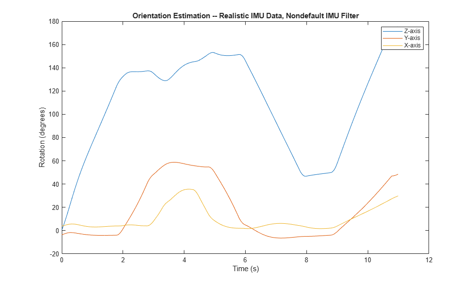
The ability of the imufilter to track the ground-truth data is significantly reduced when modeling a realistic IMU. To improve performance, modify properties of your imufilter object. These values were determined empirically. Run the loop again and plot the orientation estimate over time.
aFilter.GyroscopeNoise          = 7.6154e-7;
aFilter.AccelerometerNoise      = 0.0015398;
aFilter.GyroscopeDriftNoise     = 3.0462e-12;
aFilter.LinearAccelerationNoise = 0.00096236;
aFilter.InitialProcessNoise     = aFilter.InitialProcessNoise*10;

orientationNondefault = zeros(numSamples,1,'quaternion');
for i = 1:numSamples
    [accelBody,gyroBody] = IMU(accNED(i,:),angVelNED(i,:),orientationNED(i,:));

    orientationNondefault(i) = aFilter(accelBody,gyroBody);
end
release(aFilter)

figure(3)
plot(t,eulerd(orientationNondefault,'ZYX','frame'))
xlabel('Time (s)')
ylabel('Rotation (degrees)')
title('Orientation Estimation -- Realistic IMU Data, Nondefault IMU Filter')
legend('Z-axis','Y-axis','X-axis')
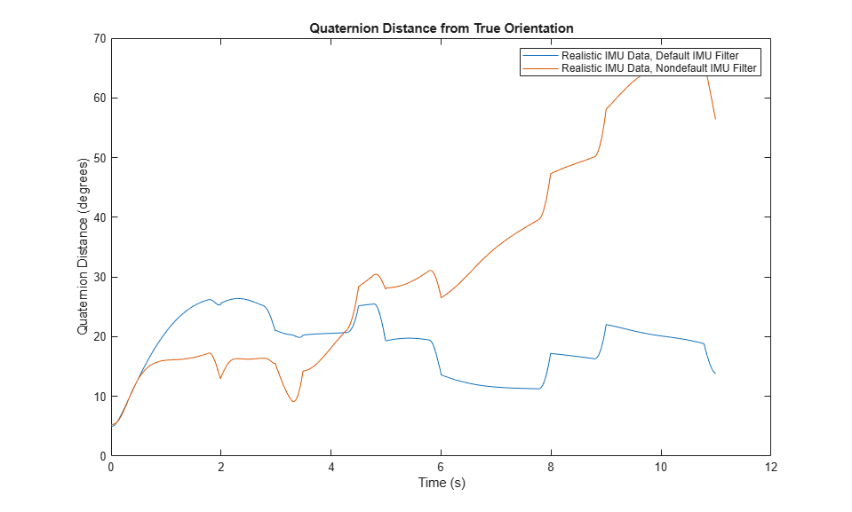
To quantify the improved performance of the modified imufilter, plot the quaternion distance between the ground-truth motion and the orientation as returned by the imufilter with default and nondefault properties.
qDistDefault = rad2deg(dist(orientationNED,orientationDefault));
qDistNondefault = rad2deg(dist(orientationNED,orientationNondefault));

figure(4)
plot(t,[qDistDefault,qDistNondefault])
title('Quaternion Distance from True Orientation')
legend('Realistic IMU Data, Default IMU Filter', ...
       'Realistic IMU Data, Nondefault IMU Filter')
xlabel('Time (s)')
ylabel('Quaternion Distance (degrees)')


Algorithms
Tip
In the following algorithm description, variables in italic fonts are inputs or outputs
of the imuSensor object. Variables in bold fonts are properties of the
imuSensor. Variables in normal fonts are properties of the accelparams, gyroparams, or magparams object.
The following algorithm description assumes an NED navigation frame. The accelerometer model
uses the ground-truth orientation and acceleration inputs and the imuSensor
and accelparams properties to
model accelerometer readings.

To obtain the total acceleration (totalAcc), the acceleration is preprocessed by negating and adding the gravity constant vector (g= [0; 0; 9.8] m/s2 assuming an NED frame) as:
The acceleration term is negated to obtain zero
total acceleration readings when the accelerometer is in a free fall. The
acceleration term is also known as the specific force.
Then the total acceleration is converted from the local navigation frame to the sensor frame using:
If the orientation is input in quaternion form, it is converted to a rotation matrix before processing.
The ground-truth acceleration in the sensor frame, a, passes through the bulk model, which adds axes misalignment and bias:
where ConstantBias is a property of accelparams, and α1, α2, and α3 are given by the first, second, and third elements of the AxesMisalignment property of accelparams.
The bias instability drift β1 is modeled as white noise biased and then filtered:
where k is the discrete time step index, BiasInstability is
a property of accelparams,
w is white noise that follows a normal distribution of mean 0 and
variance of 1. The discrete time step size is the reciprocal of the SampleRate
property. [g1,
g2, …,
gn+1] are the
denominator coefficients specified in the
BiasInstabilityCoefficients property of the accelparams object.
[f1,
f2, …,
fm+1] are the
numerator coefficients of the BiasInstabilityCoefficients property.
n and m are the orders of the denominator and
numerator coefficients, respectively.
White noise drift is modeled by multiplying elements of the white noise random stream by the standard deviation:
where w is white noise that follows a normal
distribution of mean 0 and variance of 1, SampleRate is an
imuSensor property, and NoiseDensity is an
accelparams property.
The scale variable s = 2 if the NoiseType
property of the accelparams object is
double-sided and s = 1 if the NoiseType
property is single-sided.
The random walk drift is modeled by biasing elements of the white noise random stream and then filtering:
where k is the discrete time step index, RandomWalk is a
property of accelparams, SampleRate is a
property of imuSensor, w is white noise that follows
a normal distribution of mean 0 and variance of 1. The discrete time step size is the
reciprocal of the SampleRate
property. The scale variable s = 2 if the
NoiseType property of the accelparams object is
double-sided and s = 1 if the NoiseType
property is single-sided.
The environmental drift noise is modeled by multiplying the temperature difference from a standard with the temperature bias:
where Temperature is a property of imuSensor, and TemperatureBias is a property of accelparams. The constant 25 corresponds to a standard temperature.
The temperature scale factor error is modeled as:
where Temperature is a property of imuSensor, and TemperatureScaleFactor is a property of accelparams. The constant 25 corresponds to a standard temperature.
The quantization is modeled by first saturating the continuous signal model:
and then setting the resolution:
where MeasurementRange is a property of accelparams.
The following algorithm description assumes an NED navigation frame. The gyroscope model uses
the ground-truth orientation, acceleration, and angular velocity inputs, and the
imuSensor and gyroparams
properties to model accelerometer readings.

The ground-truth angular velocity is converted from the local frame to the sensor frame using the ground-truth orientation:
If the orientation is input in quaternion form, it is converted to a rotation matrix before processing.
The ground-truth angular velocity in the sensor frame, a, passes through the bulk model, which adds axes misalignment and bias:
where ConstantBias is a property of gyroparams, and α1, α2, and α3 are given by the first, second, and third elements of the AxesMisalignment property of gyroparams.
The bias instability drift β1 is modeled as white noise biased and then filtered:
where k is the discrete time step index, BiasInstability is
a property of gyroparams,
w is white noise that follows a normal distribution of mean 0 and
variance of 1. The discrete time step size is the reciprocal of the SampleRate
property. [g1,
g2, …,
gn+1] are the
denominator coefficients specified in the
BiasInstabilityCoefficients property of the gyroparams object.
[f1,
f2, …,
fm+1] are the
numerator coefficients of the BiasInstabilityCoefficients property.
n and m are the orders of the denominator and
numerator coefficients, respectively.
White noise drift is modeled by multiplying elements of the white noise random stream by the standard deviation:
where w is white noise that follows a normal
distribution of mean 0 and variance of 1, SampleRate is an
imuSensor property, and NoiseDensity is an
gyroparams property.
The scale variable s = 2 if the NoiseType
property of the gyroparams object is
double-sided and s = 1 if the NoiseType
property is single-sided.
The random walk drift is modeled by biasing elements of the white noise random stream and then filtering:
where k is the discrete time step index, RandomWalk is a
property of gyroparams, SampleRate is a
property of imuSensor, and w is white noise that
follows a normal distribution of mean 0 and variance of 1. The discrete time step size
is the reciprocal of the SampleRate
property. The scale variable s = 2 if the
NoiseType property of the gyroparams object is
double-sided and s = 1 if the NoiseType
property is single-sided.
The environmental drift noise is modeled by multiplying the temperature difference from a standard with the temperature bias:
where Temperature is a property of imuSensor, and TemperatureBias is a property of gyroparams. The constant 25 corresponds to a standard temperature.
The acceleration bias drift is modeled by multiplying the acceleration input and acceleration bias:
where AccelerationBias is
a property of gyroparams.
The temperature scale factor error is modeled as:
where Temperature is a property of imuSensor, and TemperatureScaleFactor is a property of gyroparams. The constant 25 corresponds to a standard temperature.
The quantization is modeled by first saturating the continuous signal model:
and then setting the resolution:
where MeasurementRange is a property of gyroparams.
The following algorithm description assumes an NED navigation frame. The magnetometer model
uses the ground-truth orientation and acceleration inputs, and the
imuSensor and magparamsmagparams
properties to model magnetometer readings.

The ground-truth acceleration is converted from the local frame to the sensor frame using the ground-truth orientation:
If the orientation is input in quaternion form, it is converted to a rotation matrix before processing.
The ground-truth acceleration in the sensor frame, a, passes through the bulk model, which adds axes misalignment and bias:
where ConstantBias is a property of magparams, and α1, α2, and α3 are given by the first, second, and third elements of the AxesMisalignment property of magparams.
The bias instability drift β1 modeled as white noise biased and then filtered:
where k is the discrete time step index, BiasInstability is
a property of magparams,
w is white noise that follows a normal distribution of mean 0 and
variance of 1. The discrete time step size is the reciprocal of the SampleRate
property. [g1,
g2, …,
gn+1] are the
denominator coefficients specified in the
BiasInstabilityCoefficients property of the magparams object.
[f1,
f2, …,
fm+1] are the
numerator coefficients of the BiasInstabilityCoefficients property.
n and m are the orders of the denominator and
numerator coefficients, respectively.
White noise drift is modeled by multiplying elements of the white noise random stream by the standard deviation:
where w is white noise that follows a normal
distribution of mean 0 and variance of 1, SampleRate is an
imuSensor property, and NoiseDensity is an
magparams property.
The scale variable s = 2 if the NoiseType
property of the magparams object is
double-sided and s = 1 if the NoiseType
property is single-sided.
The random walk drift is modeled by biasing elements of the white noise random stream and then filtering:
where k is the discrete time step index, RandomWalk is a
property of magparams, SampleRate is a
property of imuSensor, w is white noise that follows
a normal distribution of mean 0 and variance of 1. The discrete time step size is the
reciprocal of the SampleRate
property. The scale variable s = 2 if the
NoiseType property of the magparams object is
double-sided and s = 1 if the NoiseType
property is single-sided.
The environmental drift noise is modeled by multiplying the temperature difference from a standard with the temperature bias:
where Temperature is a property of imuSensor, and TemperatureBias is a property of magparams. The constant 25 corresponds to a standard temperature.
The temperature scale factor error is modeled as:
where Temperature is a property of imuSensor, and TemperatureScaleFactor is a property of magparams. The constant 25 corresponds to a standard temperature.
The quantization is modeled by first saturating the continuous signal model:
and then setting the resolution:
where MeasurementRange is a property of magparams.
References
[1] IEEE. IEEE Standard Specification Format Guide and Test Procedure for Single-Axis Laser Gyros. IEEE Std 647-2006. New York: Institute of Electrical and Electronics Engineers, 2006.
[2] MEMS Industry Group. TSim Library and Manual. Accessed June 13, 2024. https://github.com/memsindustrygroup/TSim.