Debug IP Core Using FPGA Data Capture
This example shows how to debug an IP core you generate in HDL Coder™ using only FPGA Data Capture as well as both AXI Manager and FPGA Data Capture together. This example also shows how to capture a large amount of data to external memory using FPGA Data Capture.
Requirements
AMD® Zynq® UltraScale+™ MPSoC ZCU102 Evaluation Kit. For information on setting up the ZCU102 hardware, see Get Started with IP Core Generation from Simulink Model
HDL Coder Support Package for AMD FPGA and SoC Devices
HDL Verifier™ Support Package for AMD FPGA and SoC Devices
AMD Vivado® Design Suite, with a supported version listed in the HDL Language Support and Supported Third-Party Tools and Hardware
Introduction
Monitoring IP core internal signals while a design is running on real hardware is useful because you can debug and analyze the design. This example illustrates how to use the FPGA Data Capture to capture internal signals of the generated IP core in MATLAB®.
This example shows how to use FPGA Data Capture in blocking and nonblocking modes. For more information on capture modes, see CaptureMode (HDL Verifier). Nonblocking mode allows simultaneous use of AXI Manager and FPGA Data Capture over a JTAG interface. Blocking mode suspends MATLAB execution, so you cannot use other applications when you use this mode. By contrast, nonblocking mode allows you to use AXI Manager to configure the IP core while FPGA Data Capture captures data from the hardware.
This example also shows how to use FPGA Data Capture to capture a large amount of data to external memory. You can configure the memory type for storing captured data as either internal memory or external memory. Internal memory uses internal BRAM resources to store captured data, while external memory uses external DDR memory connected to the FPGA for storage. You can capture a large number of samples depending on the size of external DDR memory available on your target board. FPGA Data Capture supports external memory only for an AMD device over a JTAG, PS Ethernet, or USB Ethernet connection.
Open the model.
open_system('hdlcoder_led_blinking_data_capture');

This example implements the led_counter subsystem on the hardware. This subsystem models a counter that causes LEDs to blink on the hardware. Two input ports, Blink_frequency and Blink_direction, are control ports that determine the LED blink frequency and direction, respectively. The output port LED connects to the LEDs on the hardware. You can use the output port Read_back to read data back to MATLAB.
In the led_counter subsystem, several internal signals are test points. HDL Coder routes those internal signals out of the DUT and into the IP core wrapper so that the signals can be connected to the FPGA Data Capture HDL IP.
open_system('hdlcoder_led_blinking_data_capture/led_counter');

This example uses the Default system reference design to capture data to internal memory over a JTAG connection and the Default system with data capture with external DDR4 memory access reference design to capture a large amount of data to external memory over a PS Ethernet connection.
This figure shows a high-level block diagram of the Default system with data capture with external DDR4 memory access reference design architecture.

In this architecture, the HDL DUT IP corresponds to the IP core generated from the IP Core Generation workflow. The HDL Workflow Advisor adds the JTAG AXI Manager and FPGA Data Capture IP blocks provided by HDL Verifier to the reference design during the IP Core Generation workflow. Other blocks in the architecture represent the predefined reference design. After you run the FPGA design on the board, use the JTAG AXI Manager IP to configure the HDL DUT IP. The FPGA Data Capture IP captures the internal signals of the HDL DUT IP to external memory via the AXI4 Master interface and reads them back to MATLAB.
You can integrate the FPGA Data Capture IP core with the AXI4 Master interface into your own custom reference design by using the addFPGADataCaptureInterface method of the hdlcoder.ReferenceDesign class.
Generate HDL IP Core
Start HDL Workflow Advisor from the model and run through the IP Core Generation workflow. For a step-by-step guide, see Get Started with IP Core Generation from Simulink Model.
1. In step 1.1, set Target workflow to IP Core Generation and Target platform to Xilinx Zynq UltraScale+ MPSoC ZCU102 Evaluation Kit. Click Run This Task.
2. In step 1.2, to capture data to internal BRAM memory, set Reference design to Default system. Set Insert AXI Manager (HDL Verifier required) and FPGA Data Capture (HDL Verifier required) to JTAG. Click Run This Task.

To capture a large amount of data to external DDR memory, set Reference design to Default system with data capture with external DDR4 memory access. Set Insert AXI Manager (HDL Verifier required) to JTAG and FPGA Data Capture (HDL Verifier required) to PS Ethernet. Click Run This Task.

3. In step 1.3, select Enable HDL DUT output port generation for test points.
4. In step 1.3, set the interface of the blinkfrequency, blinkdirection, led_output, and count ports to FPGA Data Capture. Click Run This Task.

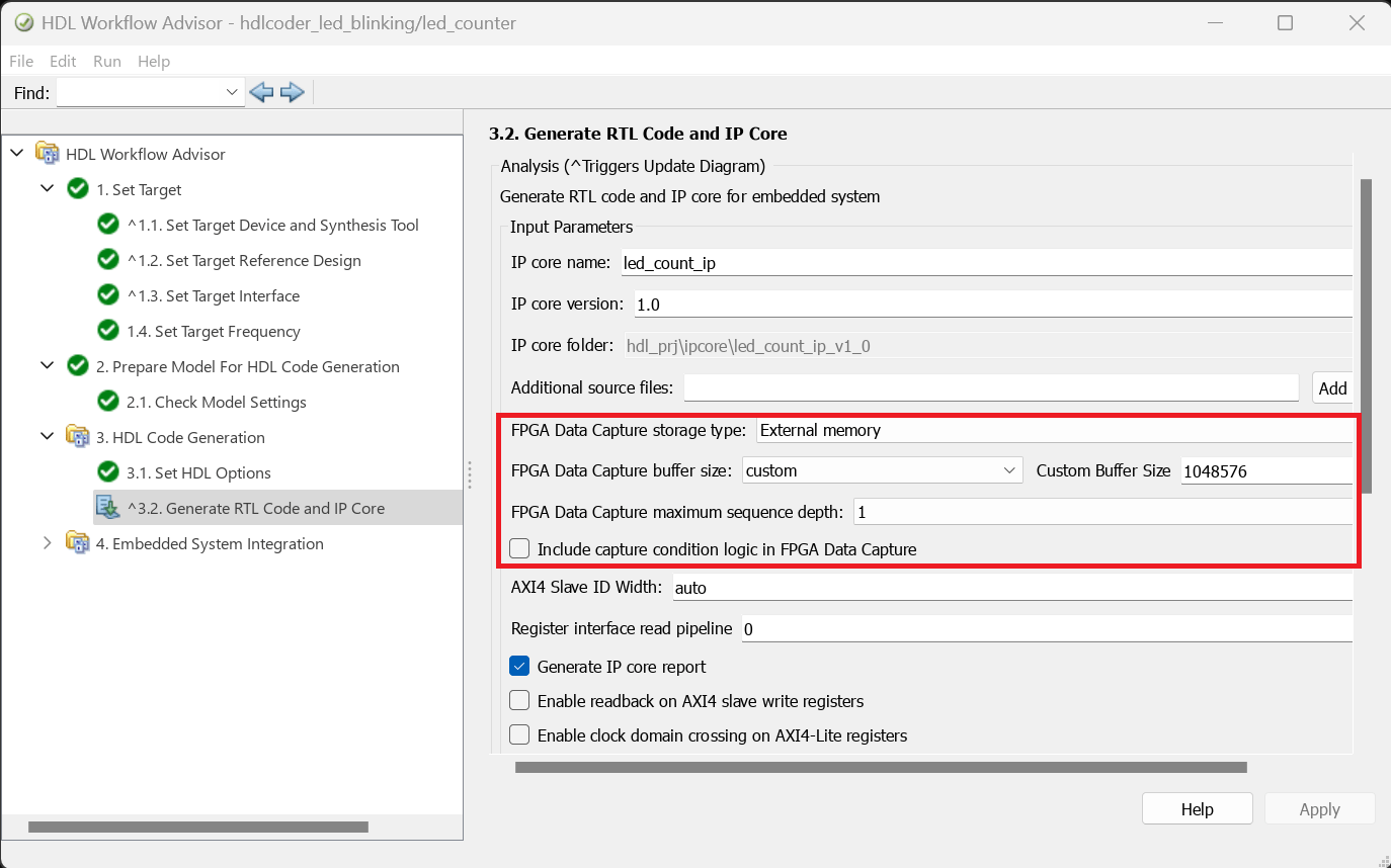
5. Run through the remaining workflow steps till step 3.1. In step 3.2, you can configure these FPGA Data Capture IP parameters: FPGA Data Capture storage type, FPGA Data Capture buffer size, FPGA Data Capture maximum sequence depth, and Include capture condition logic in FPGA Data Capture.
Use the default values for these parameters to capture debugging data to internal BRAM memory.

Set FPGA Data Capture storage type to External memory and FPGA Data Capture buffer size to 1048576 in order to capture data to external DDR memory. Click Run This Task.
6. Run through the remaining workflow steps to generate the HDL IP and program the target device.
Capture and Display Data from IP Core
Next, capture data from the Zynq UltraScale+ MPSoC board.
Locate the FPGA Data Capture launch script. For this example, the script is in your HDL code generation directory: hdl_prj/ip_core/led_count_ip_v1_0/fpga_data_capture/launchDataCaptureApp.m. You can also locate this script in the code generation report.
Run the launchDataCaptureApp script in MATLAB. Add the script directory to the MATLAB path or change the current working folder.
Capture Data in Blocking Mode

Execute the script to launch the FPGA Data Capture tool. By default, FPGA Data Capture works in blocking mode. To capture data from the FPGA without setting a trigger condition, click Capture Data.
Alternatively, you can capture data with a trigger condition. For example, set the trigger condition led_counter == 0 and the trigger position 32. Then, click Capture Data again.

Capture Data in Nonblocking Mode
Execute the script to launch the FPGA Data Capture tool and create the fpgadc_obj object in the workspace. Change the capture mode to nonblocking by executing the following command at the MATLAB command prompt.
fpgadc_obj.CaptureMode = 'nonblocking';
FPGA Data Capture in nonblocking mode allows simultaneous use of FPGA Data Capture and AXI Manager. For more information, see Simultaneous Use of FPGA Data Capture and AXI Manager (HDL Verifier). Now set a trigger condition where tp_blinkdirection == 1 and set a trigger position of 64. Then, click Capture Data.
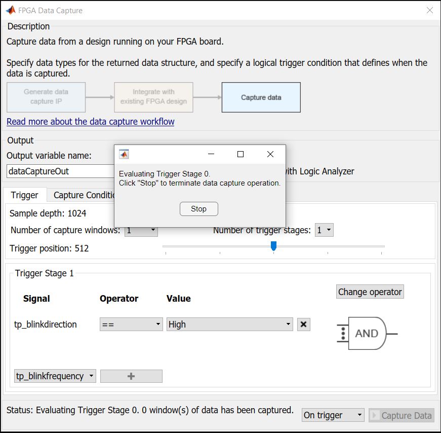
FPGA Data Capture waits for the trigger condition. As FPGA Data Capture allows AXI Manager to perform read and write operations in nonblocking mode.
Next, in FPGA Data Capture, set tp_blinkdirection to High. Then, create an AXI Manager object in MATLAB.
axi_manager_obj = aximanager('AMD');
axi_manager_obj.writememory('0x40010104',1);
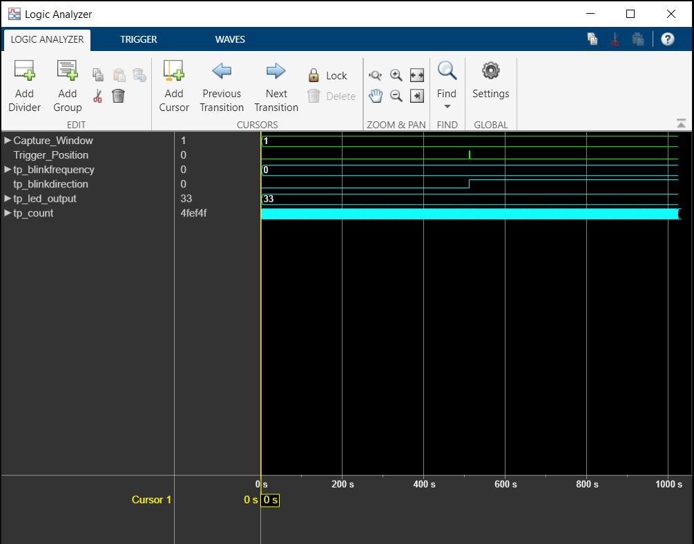
FPGA Data Capture captures the data in the Logic Analyzer. The figure shows the change in the blink direction.
Capture Large Data to External DDR Memory
This example captures a large amount of data over the PS Ethernet interface. Execute the script to launch the FPGA Data Capture tool and create the fpgadc_obj object in the workspace.
Specify the internet protocol (IP) address of the Ethernet port on the hardware board by using the DeviceAddress property.
fpgadc_obj.DeviceAddress = '10.10.10.15'
Check the base address of the data capture HDL IP core (CaptureBaseAddress) and the base address of the external DDR memory (MemoryBaseAddress). These must match the addresses in the plugin_rd reference design definition file.
To capture data from the FPGA without setting a trigger condition, click Capture Data.
Alternatively, you can capture data with a trigger condition. For example, set the trigger condition led_counter == 0. Then, create an AXI Manager object in MATLAB.
axi_manager_obj = aximanager('AMD');
axi_manager_obj.writememory('0x40000100',uint32(15));
Then, click Capture Data in FPGA Data Capture app.
Note: The Trigger position and Number of capture windows parameters are disabled for the external memory storage type.

See Also
Topics
- Data Capture Workflow (HDL Verifier)
- Capture Temperature Sensor Data from AMD FPGA Board Using FPGA Data Capture (HDL Verifier)