phased.LOSChannel
Narrowband LOS propagation channel
Description
The phased.LOSChannel models the propagation of
narrowband electromagnetic signals through a line-of-sight (LOS) channel from a source
to a destination. In an LOS channel, propagation paths are straight lines from point to
point. The propagation model in the LOS channel includes free-space attenuation in
addition to attenuation due to atmospheric gases, rain, fog, and clouds. You can use
phased.LOSChannel to model the propagation of
signals between multiple points simultaneously.
While the System object™ works for all frequencies, the attenuation models for atmospheric gases and rain are valid for electromagnetic signals in the frequency range 1–1000 GHz only. The attenuation model for fog and clouds is valid for 10–1000 GHz. Outside these frequency ranges, the System object uses the nearest valid value.
The phased.LOSChannel
System object applies range-dependent time delays to the signals, as well as gains or
losses. When either the source or destination is moving, the System object applies Doppler shifts.
Like the phased.FreeSpace
System object, the phased.LOSChannel
System object supports two-way propagation.
To create and use a narrowband channel:
Create the
phased.LOSChannelobject and set its properties.Call the object with arguments, as if it were a function.
To learn more about how System objects work, see What Are System Objects?
Creation
Description
channel = phased.LOSChannelchannel.
channel = phased.LOSChannel(Name=Value)channel, with each specified property
Name set to the specified Value.
You can specify additional name and value pair arguments in any order as
(Name1=Value1,...,NameN=ValueN).
Properties
Usage
Description
prop_sig = channel(sig,origin_pos,dest_pos,origin_vel,dest_vel)prop_sig, when a narrowband
signal, sig, propagates through a line-of-sight (LOS)
channel from a source located at the origin_pos position to
a destination at the dest_pos position. Only one of the
origin_pos or dest_pos arguments
can specify multiple positions. The other must contain a single position. The
velocity of the signal origin is specified in origin_vel
and the velocity of the signal destination is specified in
dest_vel. The dimensions of
origin_vel and dest_vel must match
the dimensions of origin_pos and
dest_pos, respectively.
Electromagnetic fields propagating through an LOS channel can be polarized or
nonpolarized. For nonpolarized fields, the propagating signal field,
sig, is a vector or matrix. For polarized fields,
sig is an array of structures. The structure elements
represent an electric field vector in Cartesian form.
Input Arguments
Output Arguments
Object Functions
To use an object function, specify the
System object as the first input argument. For
example, to release system resources of a System object named obj, use
this syntax:
release(obj)
Examples
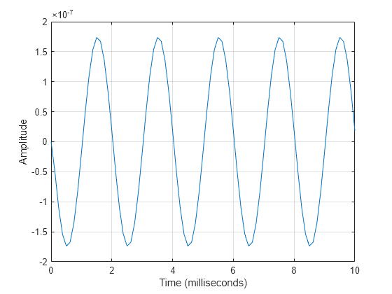
Propagate a sinusoidal signal in a line of sight (LOS) channel from a radar at (1000,0,0) meters to a target at (10000,4000,500) meters. Assume the signal propagates in medium fog specified by a liquid water density of 0.05 . Assume that the radar and the target are stationary. The signal carrier frequency is 10 GHz. The signal frequency is 500 Hz and the sample rate is 8.0 kHz.
Set up the transmitted signal.
fs = 8.0e3;
dt = 1/fs;
fsig = 500.0;
fc = 10.0e9;
t = [0:dt:.01];
sig = sin(2*pi*fsig*t);
Set the liquid water density and specify the LOS channel System object™.
lwd = 0.05;
channel = phased.LOSChannel('SampleRate',fs,'SpecifyAtmosphere',true,...
    'LiquidWaterDensity',lwd,'OperatingFrequency',fc);
Set the origin and destination of the signal.
xradar = [1000,0,0].';
vradar = [0,0,0].';
xtgt = [10000,4000,500].';
vtgt = [0,0,0].';
Propagate the signal from origin to destination and plot the result.
prog_sig = channel(sig.',xradar,xtgt,vradar,vtgt);
plot(t*1000,real(prog_sig))
grid
xlabel('Time (milliseconds)')
ylabel('Amplitude')
Propagate a polarized electromagnetic wave radiating from a short-dipole antenna element. The dipole is rotated 30° around the y-axis. Set the orientation of the local axis to coincide with the dipole. Assume the dipole radiates at 30.0 GHz. Propagate the signal toward a target approximately 10 km away.
Create the short-dipole antenna element and radiator System objects. Set the Polarization property to 'Combined' to generate polarized waves.
freq = 30.0e9;
c = physconst('LightSpeed');
antenna = phased.ShortDipoleAntennaElement('FrequencyRange',[100e6 40e9], ...
    'AxisDirection','Z');
radiator = phased.Radiator('Sensor',antenna, ...
    'PropagationSpeed',c, ...
    'OperatingFrequency',freq, ...
    'Polarization','Combined', ...
    'WeightsInputPort',false);
Create a signal to radiate. The signal envelope consists of several cycles of a 4 kHz sinusoid with amplitude set to unity. Set the sampling frequency to 1 MHz.
fsig = 4.0e3;
fs = 1.0e6;
t = [1:1000]/fs;
signal = sin(2*pi*fsig*t');
laxes = roty(30)*eye(3,3);
Use a phased.FreeSpace System object™ to propagate the field from the origin to the destination in free space.
fschannel = phased.FreeSpace('PropagationSpeed',c,...
    'OperatingFrequency',freq,...
    'TwoWayPropagation',false,...
    'SampleRate',fs);
Use a phased.LOSChannel System object to propagate the field from the origin to the destination in the LOS channel. Attenuation is due to atmospheric gases and fog.
loschannel = phased.LOSChannel('PropagationSpeed',c,...
    'OperatingFrequency',freq,...
    'TwoWayPropagation',false,...
    'SampleRate',fs,'SpecifyAtmosphere',true,'LiquidWaterDensity',0.5);
Set the signal origin, signal origin velocity, signal destination, and signal destination velocity.
source_pos = [0;0;0];
target_pos = [10000;200;0];
source_vel = [0;0;0];
target_vel = [0;0;0];
[~,radiatingAngles] = rangeangle(target_pos,source_pos,laxes);
Radiate the signal towards the target. The radiated signal is a struct containing the polarized field.
rad_sig = radiator(signal,radiatingAngles,laxes);
Propagate the signals to the target in free space.
prop_sig = fschannel(rad_sig,source_pos,target_pos,...
    source_vel,target_vel);
Propagate the signals to the target in the LOS channel.
prop_att_sig = loschannel(rad_sig,source_pos,target_pos,...
    source_vel,target_vel);
Plot the z-components of both the free-space and LOS-channel-propagated signals.
plot(1e6*t,real(prop_sig.Z),1e6*t,real(prop_att_sig.Z))
grid
xlabel('Time (\mu sec)')
legend('z_{fsp}','z_{los}')

The LOS channel signal is attenuated as compared to the free-space signal.
More About
References
[1] Radiocommunication Sector of the International Telecommunication Union. Recommendation ITU-R P.676-10: Attenuation by atmospheric gases. 2013.
[2] Radiocommunication Sector of the International Telecommunication Union. Recommendation ITU-R P.840-6: Attenuation due to clouds and fog. 2013.
[3] Radiocommunication Sector of the International Telecommunication Union. Recommendation ITU-R P.838-3: Specific attenuation model for rain for use in prediction methods. 2005.
[4] Seybold, J. Introduction to RF Propagation. New York: Wiley & Sons, 2005.
[5] Skolnik, M. Introduction to Radar Systems, 3rd Ed. New York: McGraw-Hill, 2001.
Extended Capabilities
Version History
Introduced in R2016a