disparitySGM
Compute disparity map through semi-global matching
Syntax
Description
disparityMap = disparitySGM(I1,I2)I1 and
I2, by using semi-global matching (SGM) method. To know more about
rectifying stereo images, see Image Rectification.
[
additionally returns the actual values of the disparity range used to estimate disparity,
which may differ from those provided using the disparityMap,disparityRangeUsed] = disparitySGM(I1,I2)DisparityRange
name-value argument.
___ = disparitySGM(
specifies additional options using one or more name-value pair arguments along with any of
the previous syntaxes.I1,I2,Name,Value)
Examples
Load a rectified stereo pair image.
I1 = imread("rectified_left.png");
I2 = imread("rectified_right.png");
Create the stereo anaglyph of the rectified stereo pair image and display it. You can view the image in 3-D by using red-cyan stereo glasses.
A = stereoAnaglyph(I1,I2);
figure
imshow(A)
title("Red-Cyan composite view of the rectified stereo pair image")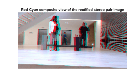
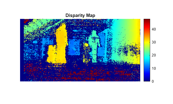
Convert the rectified input color images to grayscale images.
J1 = im2gray(I1);
J2 = im2gray(I2);
Compute the disparity map through semi-global matching. Specify the range of disparity as [0, 48], and the minimum value of uniqueness as 20.
disparityRange = [0 48];
disparityMap = disparitySGM(J1,J2,"DisparityRange",disparityRange,"UniquenessThreshold",20);
Display the disparity map. Set the display range to the same value as the disparity range.
figure
imshow(disparityMap,disparityRange)
title("Disparity Map")
colormap jet
colorbar
Input Arguments
Name-Value Arguments
Output Arguments
More About
Tips
Ensure accurate rectification — Imperfect rectification can significantly degrade the quality of the disparitySGM function results. Use the
rectifyStereoImagesfunction to rectify the input stereo image pairI1andI2, so that the corresponding points are on the same rows. Use thestereoAnaglyphfunction to inspect the rectification results by creating an anaglyph image.Apply post-processing — For better results, improve disparity maps by applying image processing operations such as median filtering (
medfilt2), hole filling (imfill), or bilateral filtering (imbilatfilt).Explore deep learning-based alternatives — For well-rectified, narrow-baseline stereo setups where classical SGM struggles with texture-less regions or repeated patterns, try
opticalFlowRAFTas a deep learning-based alternative. For more information on comparison between classical SGM and RAFT deep learning model, see Compare RAFT Optical Flow and Semi-Global Matching for Stereo Reconstruction.
Algorithms
The range of disparity must be chosen to cover the minimum and the maximum amount of
horizontal shift between the corresponding pixels in the rectified stereo pair image. You
can determine the approximate horizontal shift values from the stereo anaglyph of the stereo
pair image. Compute the stereo anaglyph of the rectified images by using the stereoAnaglyph function. Display the stereo anaglyph in the Image
Viewer app. To measure the amount of horizontal shift between the corresponding
points in the stereo pair image, select Measure Distance
from the Tools menu in Image Viewer. Choose the
minimum and maximum disparity values for the range of disparity based on this measurement.
For example, this figure displays the stereo anaglyph of a rectified stereo pair image and the horizontal shift values measured between the corresponding points in the stereo pair image. The minimum and maximum shift values are computed as 12.3101 and 32.3757 respectively. Based on these values, the range of disparity can be chosen as [0, 48].

References
[1] Hirschmuller, H. "Accurate and Efficient Stereo Processing by Semi-Global Matching and Mutual Information." In Proceedings of the IEEE Conference on Computer Vision and Pattern Recognition (CVPR), pp. 807-814. San Diego, CA: IEEE, 2005.