Estimate Camera-to-IMU Transformation Using Extrinsic Calibration
R2026bThis example shows the process of extrinsic calibration between a camera and an IMU to estimate the SE(3) homogeneous transformation, also known as a rigid transformation. This process is necessary to ensure accurate performance of Visual-Inertial Odometry (VIO) and Visual-Inertial Simultaneous Localization and Mapping (VI-SLAM) algorithms, which are integral components of a Visual-Inertial Navigation System (VINS). Visual-inertial navigation systems rely on these algorithms for precise state estimation during mapping and autonomous navigation workflows.
Overview
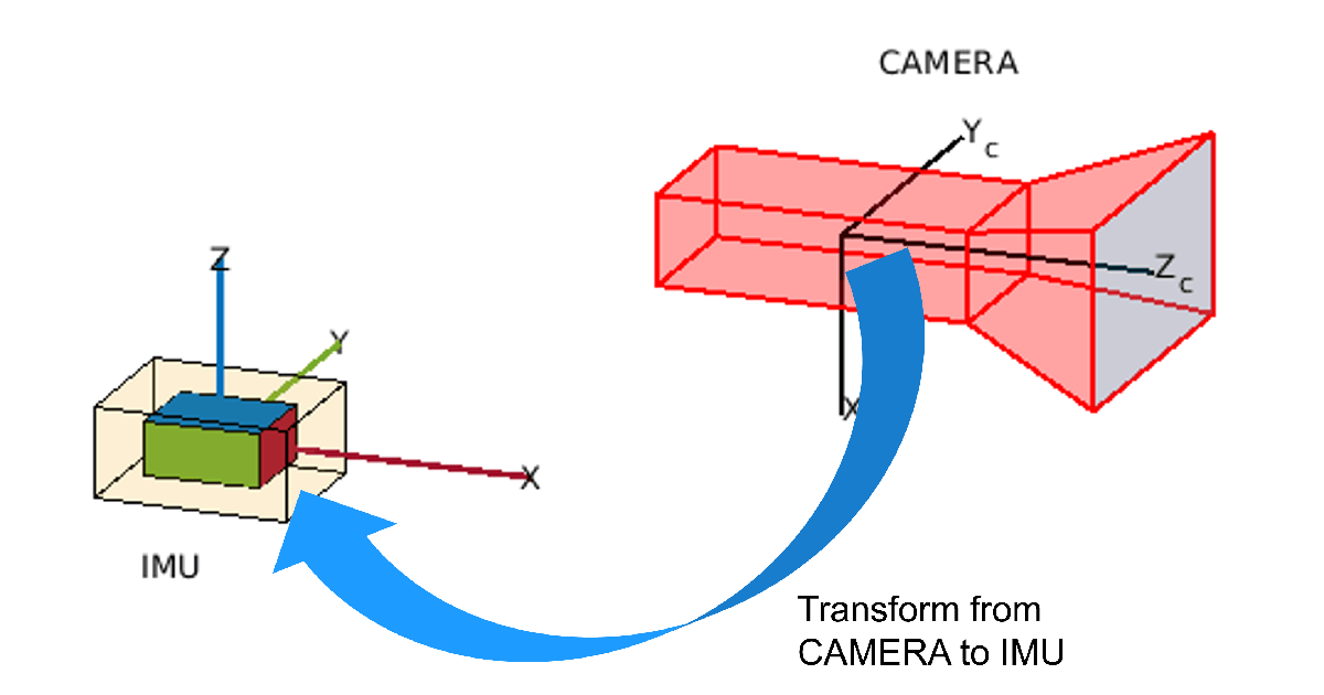
The goal of camera-IMU extrinsic calibration is to accurately determine the SE(3) transformation that defines the spatial relationship between the camera and the IMU. The quality and variety of the calibration data determine the reliability of this transformation. Therefore, it is essential to assess whether the estimated transformation is valid and reliable for use in subsequent workflows. This example guides you through the steps of estimating and validating the extrinsic transformation. This figure visualizes the camera-to-IMU transformation, providing a visual reference for understanding the extrinsic calibration process.
Prerequisites
This example assumes that
Camera-IMU calibration data is collected. Whenever sensor setup movement is possible follow data collection recommendations in What Is Camera-IMU Calibration? (Navigation Toolbox) to collect data. Otherwise move the sensor setup randomly to rotate and accelerate along possible directions. Without rotations around all IMU coordinate axes, the translation estimated between camera and IMU may be wrong.
IMU measurements must be calibrated. For more information, see
accelcal(Navigation Toolbox) function.Camera intrinsic parameters are known. For more information about camera intrinsic parameters, see the Camera Calibration Parameters section of What Is Camera Calibration?.
IMU noise parameters are known or static IMU data is available. In this example you compute the required noise parameters using Allan variance analysis on 3 hours of static IMU data. For best results use IMU sequences logged at least for 3 hours. For more information about noise parameter estimation, see Inertial Sensor Noise Analysis Using Allan Variance (Navigation Toolbox).
Load the data from CameraIMUCalibrationData.mat file which is pre-computed from the ROS1 bag files static_imu_data.bag (Download: 811 MB) and camera_imu_calibration_data.bag (Download: 443 MB) contained in WPI Lidar Visual SLAM Dataset [1]. Use the helperProcessData to generate the MAT file. The mat file contains pattern detection in calibration images, IMU measurements, corresponding time stamps and camera intrinsic parameters. To read raw sensor data from ROS1 bag use helperROSReadData.
outputFolder = fullfile(tempdir,'Calibration');

dataURL = ['https://ssd.mathworks.com/supportfiles/shared_nav_vision/data/' ...
            'camera_imu_calibration.zip'];

data = helperDownloadVICalibrationData(outputFolder,dataURL);
Initialize the known camera intrinsic parameters specific to this sensor suite.
focalLength = data.CameraFocalLength;
principalPoint = data.CameraPrincipalPoint;
imageSize = data.ImageSize;
camIntrinsics = cameraIntrinsics(focalLength,principalPoint,imageSize);
Compute the sample rate of the IMU from the static IMU measurements.
imuSampleRate = ceil(1/mean(seconds(diff(data.StaticIMUMeasurements.Time))));
Use the helperComputeNoiseParamsUsingAllanVariance helper function to compute IMU noise parameters using the Allan variance method.
imuParams = helperComputeNoiseParamsUsingAllanVariance(data.StaticIMUMeasurements,imuSampleRate);
Execute Calibration
The first step in calibration process is to detect the checkerboard pattern within the calibration images. This pattern enables the calibration algorithm to determine the trajectory of the camera accurately. The checkerboard detection are pre-computed in this example. Use Computer Vision Toolbox™ function detectCheckerboardPoints to detect the pattern in input calibration images as shown below.
[patternDetections,boardSize,imagesUsed] = detectCheckerboardPoints(...
     images,HighDistortion=false,ShowProgressBar=true, ...
     PartialDetections=false);
for k = 1:size(patternDetections,3)
    patternDetections(:,:,k) = undistortPoints(patternDetectionss(:,:,k), camIntrinsics);
end
Generate a 2-D pattern of the checkerboard points based on the determined board size and square size of 0.04 meters. The pattern is assumed to be planar existing in XY plane of camera world coordinate frame. This pattern is essential as it provides easily identifiable reference points in the images. These points enable the calibration algorithm to determine the extrinsic parameters of the camera by comparing these known 3D positions of the checkerboard corners with their 2D projections on the camera's imaging plane.
squareSize = data.CheckerBoardSquareSize; % in meters
boardSize = data.CheckerBoardSize;
patternPoints = patternWorldPoints("checkerboard",boardSize,squareSize);
Estimate camera trajectory including 3-D translation and 3-D rotation in camera world frame using the generated checkerboard pattern points and checkerboard pattern detection.
ax = [];
numCameras = size(data.PatternDetections,3);
cameraPoses = repelem(rigidtform3d, numCameras, 1);
reprojectionErrors = nan(numCameras,1);
for imgId = 1:numCameras
    imagePoints = data.PatternDetections(:,:,imgId);
    valid = ~isnan(imagePoints(:,1));
    if length(find(valid)) >= 3
        % at least 3 valid points are needed for pose estimation
        imPoints = imagePoints(valid,1:2);
        Tr = estimateExtrinsics(imPoints,patternPoints(valid,1:2),camIntrinsics);
        T = extr2pose(Tr);
        worldPoints = [patternPoints(valid,1:2),zeros(length(find(valid)),1)];
        projectedPoints = world2img(worldPoints,Tr,camIntrinsics);
        reprojectionErrors(imgId) = mean(vecnorm(projectedPoints-imPoints,2,2));
        cameraPoses(imgId) = T;
        % plot camera pose estimates
        ax = helperPlotCameraPoses(ax,patternPoints,T);
    end
end
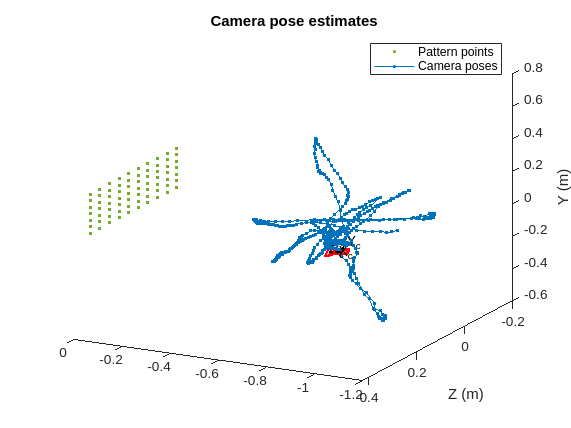
validImageIds = reprojectionErrors < 1;
Create a cameraIMUCalibrationOptions object to define the settings to use for extrinsic calibration. Set UndistortPoints to false to not apply distortion correction to the detected checkerboard points. Typically, you set it to false if the images have already been undistorted or if distortion is not a concern. The ImageTime option is set with the timestamps of the images, which is crucial for synchronizing the images with the IMU data. The CameraInformation option is set to specify larger information value of 100 instead of default value of 1. Larger information value conveys larger trust in pattern detection input.
calibOptions = cameraIMUCalibrationOptions(UndistortPoints=false, ...
                                           ImageTime=data.ImageTime(validImageIds), ...
                                           CameraInformation=100*eye(2), ...
                                           CameraPoses=cameraPoses(validImageIds));
Execute the extrinsic calibration using the estimateCameraIMUTransform (Navigation Toolbox) function. Specify the detected checkerboard points in the images, the 3D world points of the checkerboard pattern, the IMU measurements, the known camera intrinsic parameters, the IMU noise parameters, and the calibration options. The function estimates the spatial transformation between the camera and the IMU and calibration parameters that quantify the quality of the calibration, such as the re-projection errors and the estimated camera poses.
[tform,params] = estimateCameraIMUTransform(data.PatternDetections(:,:,validImageIds), ...
                                            patternPoints, ...
                                            data.IMUMeasurements, ...
                                            camIntrinsics, ...
                                            imuParams, ...
                                            calibOptions);
Validate Calibration
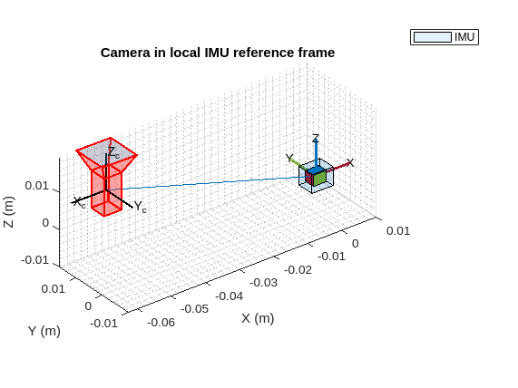
Visualize the estimated extrinsic transform and visually confirm that the transform is within the expected physical limits. The precision of the translation estimates between the camera and the IMU depends on the rotational movements captured during data acquisition. For a more accurate translation estimate, rotate the combined camera-IMU sensor setup around each of the axes of the IMU while gathering data. Note that if the data collection involves predominantly planar movements, the translation estimate along certain axes of the IMU may be inaccurate. For example, if you only move the camera-IMU setup in the xy-plane, then translation estimates involving the z-axis may be inaccurate.
showTransform(params,ScaleFactor=0.005);
To ensure the calibration results are accurate, assess the pattern point re-projection error per image and the IMU prediction error. Low values in both metrics suggest that the estimated transformation aligns the camera and IMU trajectories effectively. The re-projection and prediction errors provide a rough indication of the expected performance when utilizing the estimated transform in VIO applications. You should select the error thresholds based on the specific requirements of the VIO system in use. For instance, in this example, set the re-projection error threshold to 0.5, translation prediction error threshold to 1e-2 and rotation prediction error threshold set to 1e-3. These values are generally considered acceptable for a wide range of VIO tasks.
reprojectionErrorThreshold = 0.5;
predictionErrorThreshold = [1e-2 1e-3];
[status,info] = validate(params,reprojectionErrorThreshold,predictionErrorThreshold);
Check the calibration status. If the status flag is zero, then the calibration was successful. In this case, because it is zero, there were no issues with the calibration.
status
status =
  CameraIMUCalibrationStatus enumeration

    Success
Calibration is successful. Observe the re-projection errors and the IMU prediction errors are below expected thresholds.
Assess Re-Projection Errors
Use the showReprojectionErrors function to visualize the re-projection errors and visually identify images that are below the re-projection error threshold.
showReprojectionErrors(params,threshold=reprojectionErrorThreshold);
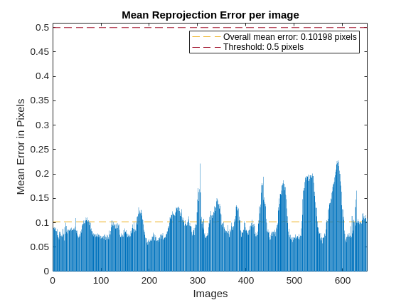
A lower re-projection error than threshold, as seen in the plot, leads to successful calibration if no other validation issues are found. A larger re-projection error leads to unsuccessful calibration. In such cases these steps may help to address these issues:
Exclude images with notably high re-projection errors from the calibration dataset and re-calibrate.
If many images exhibit high re-projection errors both before and after calibration, this could point to flawed pattern detection, possibly caused by issues such as motion blur or incomplete board visibility. In this case, consider acquiring new calibration data. For data collection recommendations, see What Is Camera-IMU Calibration? (Navigation Toolbox)
If high re-projection errors are only present post-calibration, it indicates a lack of reliability in the feature point detection of the camera during the calibration process. To improve reliability of feature point detection, consider increasing the
CameraInformationproperty within thecameraIMUCalibrationOptions.
Access IMU Prediction Errors
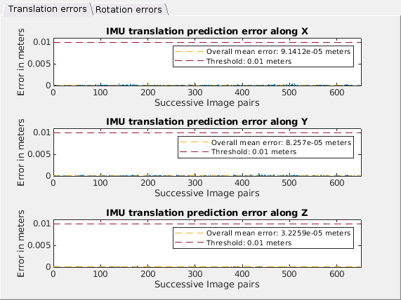
Use the showIMUPredictionErrors function to visualize IMU prediction errors and visually identify any IMU translation prediction and rotation prediction errors that are below specified thresholds. Larger prediction error may indicate misalignment between the camera and IMU trajectories. If these large prediction errors are present but all other checks passed, it indicates that the calibration dataset lacks sufficient information to accurately estimate the transformation between the camera and the IMU. Under such circumstances, you may need to gather a new set of calibration data, ensuring it captures a wider range of movements and orientations to enhance the robustness of the transformation estimate.
showIMUPredictionErrors(params,threshold=predictionErrorThreshold);
Assess IMU Bias Estimate
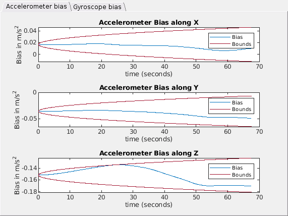
Use the showIMUBiasEstimates function to visualize the IMU Bias estimates after calibration and visually identify that the bias estimates are within the expected bounds that the calibration determined from specified IMU noise parameters. If the bias estimates exceed these bounds, this discrepancy may be due to inaccurate IMU noise parameters or excessively rapid camera movement during data collection. To resolve these calibration issues:
If the IMU bias is the sole concern, refine the IMU noise parameters.
If both the re-projection error assessment and the IMU bias value check fail, consider recapturing the calibration data. When recapturing data, operate the camera-IMU sensor setup more gradually. For more recommendations, see What Is Camera-IMU Calibration? (Navigation Toolbox)
showIMUBiasEstimates(params);
Reference
[1] WPI Lidar Visual SLAM Dataset, GitHub repository, https://github.com/WPI-APA-Lab/WPI-Lidar-Visual-SLAM-Dataset

