Perform Metrology Edge Measurements and Alignment
A crucial visual inspection task in metrology analysis is the assessment of image features to determine whether they fall within a specified acceptable range. Compared to deep learning-based approaches, measurement-based methodologies, also known as metrology workflows, offer distinct advantages. These advantages include the capability to achieve precise sub-pixel measurements of image features and the computational benefits of faster execution and easier deployment on hardware platforms.
In this example, you perform 1-D distance measurements of fill lines in soda bottles using a caliper tool, and develop a classification model for normal and anomalous fill line images. This analysis illustrates how to employ distance measurements and image registration in a visual inspection pipeline to quantify inadequate fill levels and defects in soda bottles. To learn how to perform this visual inspection pipeline during live image acquisition of bottle fill lines, see the Inspect Bottle Fill Level During Live Image Acquisition (Image Acquisition Toolbox) example.
Download Bottle Fill Line Inspection Data Set
This example uses a bottle fill line inspection data set, generated with the Image Acquisition Toolbox™ and a connected industrial camera. To re-create similar types of data acquisitions, see the createDatasetForBottleInspectionUsingIMAQ MLX file attached to this example as a supporting file.
This data set contains good and bad folders, which store the normal bottle images, and the defective or inadequately filled bottle images, respectively.
Download the data set as a ZIP file and extract the data. Specify fullDataPath as the location of the data set.
unzip("https://ssd.mathworks.com/supportfiles/vision/data/bottleFillLineInspectionDataset.zip",tempdir);
fullDataPath = fullfile(tempdir,"bottleFillLineInspectionDataset");
Perform Reference Measurement
First, establish a stable and reproducible edge measurement from the top of the cap to the fill line that can be consistently replicated across other images in the set, irrespective of lighting reflections and other potential variations in the scene.
Extract a "good" image of a non-defective and adequately filled soda bottle from the good folder.
fullDataPath = fullfile(tempdir,"bottleFillLineInspectionDataset");
goodImage = imread(fullfile(fullDataPath,"good","good.png"));
To establish a reference measurement value, measure the distance from the top of the cap to the liquid fill line. During inspection, you will compute this distance again for each image and assess it against the reference value.
Create an Image object using the imageshow function, and display the "good" image.
hIm = imageshow(goodImage);
Define the position of the profile line of the caliper measurement tool so that the profile line contains the all the relevant edges of the fill line.
referenceMeasurementPos = [1173.2, 106.7; 1167.5 1057.8];
Detect and measure the distances between the edges in the reference image with the caliper tool by using the uicaliper object. Specify the EdgeTransition name-value argument as "both" to detect both brighter to darker and darker to brighter edge transitions, and specify the MeasurementMode as "single-edge" to only detect single edges. Specify a gradient threshold of 0.02.
hCal = uicaliper(hIm,Position=referenceMeasurementPos,MeasurementMode="single-edge", ...
    GradientThreshold = 0.02,EdgeTransition="both");

Compute the distance between the first and the last detected gradient, in pixels, as the reference measurement. The caliper tool detects several additional edges between the top of the cap and the fill line which can be ignored.
refCapToFillLineDistance = hCal.Distance(end) - hCal.Distance(1)
refCapToFillLineDistance =
866.9292
In this example, the distance is measured in pixels for simplicity. However, in some workflows, using camera calibration to convert measurements into physical units like millimeters is advantageous.
Align Data to Reference Image
There is noticeable horizontal translation in the position of the bottle within the images in the data set. This variation and similar factors are challenging to control during acquisition. To address this, it is usually necessary to solve an image registration or alignment problem. This ensures that during inspection, the image is aligned with the reference image, allowing measurements to be consistently recreated relative to known structures within the image.
Create an imageDatastore object containing the data subsets of "good" and "bad" bottle images.
ds = imageDatastore(fullDataPath,IncludeSubfolders=true,LabelSource="foldernames");
dsGood = subset(ds,ds.Labels=="good");
dsBad = subset(ds,ds.Labels=="bad");
Visualize the difference in bottle position between two good images using the imshowpair function.
im1 = read(dsGood);
im2 = read(dsGood);
imshowpair(im1,im2)

Select Template Region in Reference Image
Select a template region in the reference image goodImage, the top part of the cap. This image region is expected to always be present, and can be uniquely geometrically matched across all images to infer the overall alignment of each inspected image to the reference image.
templatePos = [902 114 377 237];
capTemplate = imcrop(goodImage,templatePos);
imageshow(capTemplate)

Align Template Region
Align the template with input images using the imregcorr function. Visualize the template aligned on top of the image.
tform = imregcorr(capTemplate,im2,"translation");
templateAligned = imwarp(capTemplate,tform,OutputView=imref2d(size(im2)));
imshowpair(templateAligned,im2)
Compute Recovered Translation Value
To determine the overall translation needed to align an image with the reference image, subtract the original position of the template in the reference image from the recovered translation that aligns the template with the inspected image.
tformOverall = tform;
tformOverall.A(1:2,3) = tformOverall.A(1:2,3) - templatePos(1:2)' + 1;
To verify that overall transformation aligns the reference image with the input image, translate the image using the imwarp function. Visualize the inspected image and the reference image using the imshowpair function.
goodImageShifted = imwarp(goodImage,tformOverall,OutputView=imref2d(size(im2)));
imshowpair(im2,goodImageShifted)

In the next sections, to align a set of inspection images with the reference image using this geometric transformation method, you can use the translateImage helper function.
Perform Distance Measurement Using Recovered Alignment
To ensure consistent distance measurements across images during inspection, one approach is to create a resampled image based on the recovered geometric transformation from the previous section and then use the caliper tool to measure the distance at the same location as in the reference image. To eliminate the need for image resampling, you can directly map the caliper's position to the corresponding location in the inspection image using the recovered geometric transformation.
Display a "bad" image using the imageshow function, and use the translateImage helper function to translationally transform the position of the template region on the image. Translate the position of the caliper profile line from the reference profile line using the transformPointsForward function.
exampleBad = preview(dsBad);
hImBad = imageshow(exampleBad);
tform = translateImage(capTemplate,templatePos,exampleBad);
equivalentPos = transformPointsForward(tform,referenceMeasurementPos);
Detect and measure the distance between the edges in the "bad" image with the caliper tool by using the uicaliper object. Specify the EdgeTransition name-value argument as "both" to detect both brighter to darker and darker to brighter edge transitions, and specify the MeasurementMode as "single-edge" to only detect single edges. Specify a gradient threshold of 0.01.
hCalBad = uicaliper(hImBad,Position=equivalentPos,MeasurementMode="single-edge", ...
    GradientThreshold = 0.01,EdgeTransition="both");
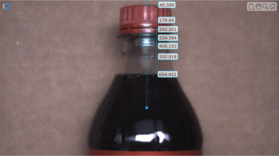
Measure the distance between the fill line and the cap top. In the case of this "bad" image, this distance is reduced because the bottle is overfilled.
exampleBadDistance = hCalBad.Distance(end) - hCalBad.Distance(1)
exampleBadDistance =
608.8235
Automate Fill Level Visual Inspection Pipeline
To automate the inspection process for the bottle image data, align each image with the reference image. Determine the equivalent measurement position, or location of the profile line, in each image and measure the fill line distance using with the caliper tool using the caliper function. Use the caliper function, instead of the uicaliper object to increase computation speed in deployment scenarios where visualization is not required. Measure the distance between the fill line and the top of the cap, and compare this measurement to an "acceptable" value. If a measurement is within a 3% tolerance of the acceptable value, it is not anomalous.
function TF = inspectFillLineDistance(capTemplate,templatePos,inspectionImage,referenceMeasurementPos,expectedDistance)
    tform = translateImage(capTemplate,templatePos,inspectionImage);
    equivalentPos = transformPointsForward(tform,referenceMeasurementPos);
    measurementData = caliper(inspectionImage,equivalentPos,MeasurementMode="single-edge", ...
        GradientThreshold = 0.01,EdgeTransition="both");
    % Compute distance between first edge (fill line) to last edge (cap top).
    measuredDist = measurementData.Distance(end) - measurementData.Distance(1);
    TF = abs(measuredDist-expectedDistance) < .03 * expectedDistance;
end
Perform Automatic Edge Visual Inspection
Perform automatic visual inspection of the fill line edge with the caliper tool on the entire data set.
Remove the reference measurement image from the data set.
dsTest = subset(ds,~contains(ds.Files,"good.png"));
isGood = false(numpartitions(dsTest),1);
Use the inspectFillLineDistance function defined in the Automate Fill Level Visual Inspection Pipeline section to inspect the fill line level in each image.
idx = 1;
while hasdata(dsTest)
    inspectionImage = read(dsTest);
    isGood(idx) = inspectFillLineDistance(capTemplate,templatePos,inspectionImage,referenceMeasurementPos,refCapToFillLineDistance);
    idx = idx + 1;
end
Evaluate the performance metrics of the measurement-based fill line inspection using the evaluateAnomalyDetection function. The function computes several metrics that evaluate the accuracy, precision, sensitivity, and specificity of the detector for the test data set.
metrics = evaluateAnomalyDetection(~isGood,dsTest.Labels=="bad",true);Evaluating anomaly detection results
------------------------------------
* Finalizing... Done.
* Data set metrics:
GlobalAccuracy MeanAccuracy Precision Recall Specificity F1Score FalsePositiveRate FalseNegativeRate
______________ ____________ _________ _______ ___________ _______ _________________ _________________
0.96667 0.97857 1 0.95714 1 0.9781 0 0.042857
The ConfusionMatrix property of metrics contains the confusion matrix for the test set. Extract the confusion matrix and display a confusion plot. The measurement-based classification model in this example is very accurate and predicts a small percentage of false positives negatives.
M = metrics.ConfusionMatrix{:,:};
confusionchart(M,["Normal","Anomaly"])
There are three missed detections reflected in the confusion matrix. Visualize one of these detections to investigate the source.
missedDetectionIndices = (dsTest.Labels=="bad") & isGood;
missedDetectionExample = read(subset(dsTest,missedDetectionIndices));
hImMissed = imageshow(missedDetectionExample);
tform = translateImage(capTemplate,templatePos,missedDetectionExample);
equivalentPos = transformPointsForward(tform,referenceMeasurementPos);
Detect and measure the distance between the edges in the image with the caliper tool by using the uicaliper object. Specify the EdgeTransition name-value argument as "both" to detect both brighter to darker and darker to brighter edge transitions, and specify the MeasurementMode as "single-edge" to only detect single edges. Specify a gradient threshold of 0.01.
measurementData = uicaliper(hImMissed,Position=equivalentPos,MeasurementMode="single-edge", ...
    GradientThreshold = 0.01,EdgeTransition="both");
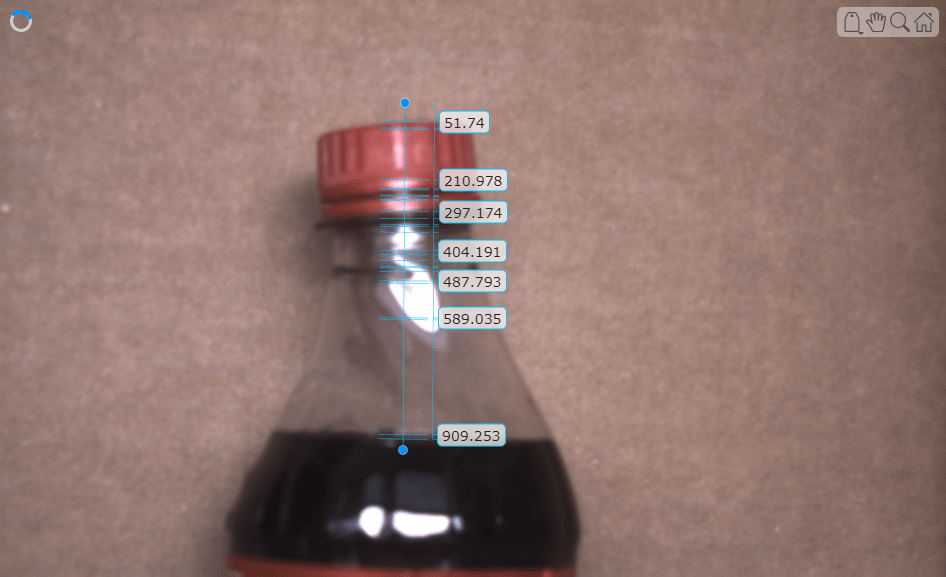
As previously mentioned in the data set creation section, some of the "bad" images in this dataset are considered "bad" due to the warping or distortion of the bottles themselves. Observe that all missed detections fall into this category, where the fill level is actually within the expected tolerance. Since the current inspection pipeline only assesses fill level, detecting this type of defect requires the integration of additional inspection logic.
Helper Functions
translateImage
function tform = translateImage(capTemplate,templatePos,inspectionImage)
tform = imregcorr(capTemplate,inspectionImage,"translation");
tform.A(1:2,3) = tform.A(1:2,3) - templatePos(1:2)' + 1;
end
See Also
caliper | uicaliper | imregcorr | transformPointsForward | evaluateAnomalyDetection | imwarp
Topics
- Inspect Bottle Fill Level During Live Image Acquisition (Image Acquisition Toolbox)