dsp.CICCompensationDecimator
Compensate for CIC decimation filter using FIR decimator
Description
You can compensate for the shortcomings of a CIC decimator, namely its passband droop and wide transition region, by following it with a compensation decimator. This System object™ lets you design and use such a filter.
To compensate for the shortcomings of a CIC filter using an FIR decimator:
Create the
dsp.CICCompensationDecimatorobject and set its properties.Call the object with arguments, as if it were a function.
To learn more about how System objects work, see What Are System Objects?
Creation
Syntax
Description
ciccompdec = dsp.CICCompensationDecimatorciccompdec, that applies an FIR decimator to each
channel of an input signal. Using the properties of the object, the decimation filter can
be designed to compensate for a preceding CIC filter.
ciccompdec = dsp.CICCompensationDecimator(decim)DecimationFactor property set to
decim.
ciccompdec = dsp.CICCompensationDecimator(cic)CICRateChangeFactor,
CICNumSections, and CICDifferentialDelay
properties specified in the dsp.CICDecimator
System object, cic.
ciccompdec = dsp.CICCompensationDecimator(cic,decim)ciccompdec, with the
CICRateChangeFactor, CICNumSections, and
CICDifferentialDelay properties specified in the
dsp.CICDecimator
System object
cic, and the DecimationFactor property set to
decim.
ciccompdec = dsp.CICCompensationDecimator(___,PropertyName=Value)FilterOrder to 16.
Properties
Usage
Syntax
Description
Input Arguments
Output Arguments
Object Functions
To use an object function, specify the
System object as the first input argument. For
example, to release system resources of a System object named obj, use
this syntax:
release(obj)
Examples
Create a dsp.CICCompensationDecimator object with default settings. While creating the object, set the NormalizedFrequency property to true so that the passband and the stopband frequencies are in normalized frequency units.
CICCompDecim = dsp.CICCompensationDecimator(...
    NormalizedFrequency=true)
CICCompDecim =
dsp.CICCompensationDecimator with properties:
CICRateChangeFactor: 2
CICNumSections: 2
CICDifferentialDelay: 1
DecimationFactor: 2
NormalizedFrequency: true
DesignForMinimumOrder: true
PassbandFrequency: 0.1667
StopbandFrequency: 0.6667
PassbandRipple: 0.1000
StopbandAttenuation: 60
Show all properties
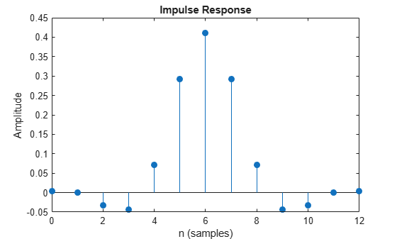
Plot the impulse response.
impz(CICCompDecim)
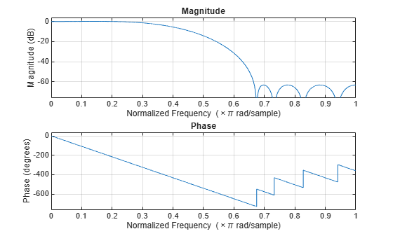
Plot the magnitude and phase responses.
freqz(CICCompDecim)
Design a compensation decimator for an existing CIC decimator having six sections and a decimation factor of 6.
CICDecim = dsp.CICDecimator(DecimationFactor=6,...
    NumSections=6)
CICDecim =
dsp.CICDecimator with properties:
DecimationFactor: 6
DifferentialDelay: 1
NumSections: 6
FixedPointDataType: 'Full precision'
Construct the compensation decimator. Specify a decimation factor of 2, an input sample rate of 16 kHz, a passband frequency of 4 kHz, and a stopband frequency of 4.5 kHz.
fs = 16e3;
fPass = 4e3;
fStop = 4.5e3;

CICCompDecim = dsp.CICCompensationDecimator(CICDecim,...
    DecimationFactor=2,PassbandFrequency=fPass,...
    StopbandFrequency=fStop,SampleRate=fs)
CICCompDecim =
  dsp.CICCompensationDecimator with properties:

      CICRateChangeFactor: 6
           CICNumSections: 6
     CICDifferentialDelay: 1
         DecimationFactor: 2
      NormalizedFrequency: false
    DesignForMinimumOrder: true
        PassbandFrequency: 4000
        StopbandFrequency: 4500
           PassbandRipple: 0.1000
      StopbandAttenuation: 60
               SampleRate: 16000

  Show all properties
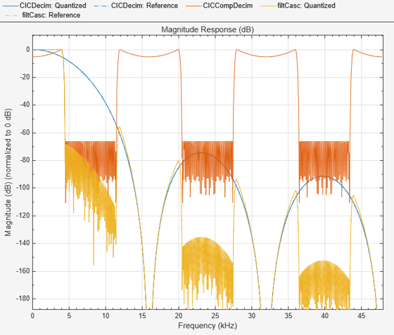
Visualize the frequency response of the cascade. Normalize all magnitude responses to 0 dB.
filtCasc = dsp.FilterCascade(CICDecim,CICCompDecim);

f = filterAnalyzer(CICDecim, CICCompDecim, filtCasc, SampleRates=[fs*6 fs fs*6], NormalizeMagnitude=true);
Apply the design to a 1200-sample random input signal. Store the decimated output along the first dimension of the y array.
x = dsp.SignalSource(fi(rand(1200,1),1,16,15),SamplesPerFrame=120);

y = fi(zeros(100,1),1,32,20);

for ind = 1:10
    x2 = CICDecim(x());
    y(((ind-1)*10)+1:ind*10,1) = CICCompDecim(x2);
end
More About
Algorithms
The response of a CIC filter is given by:
R, D, and N are the rate change factor, the differential delay, and the number of sections in the CIC filter, respectively.
After decimation, the CIC response has the form:
The normalized version of this last response is the one that the CIC compensator needs to compensate. Hence, the passband response of the CIC compensator should take the following form:
where ωp is the passband frequency of the CIC compensation filter.
Notice that when ω/2R ≪ π, the previous equation for Hciccomp(ω) can be simplified using the fact that sin(x) ≅ x:
This previous equation is the inverse sinc approximation to the true inverse passband response of the CIC filter.
Extended Capabilities
Version History
Introduced in R2014bSee Also
Functions
freqz|freqzmr|filterAnalyzer|info|cost|coeffs|outputDelay|polyphase|setInputSampleRate