DEMCON Reduces Development Time for FPGA-Controlled Surgical Instrument
“As a mechatronic systems engineer, my expertise is in control systems and their models, not HDL and FPGAs. With Model-Based Design, I can use my insight and knowledge of the controller and the system being controlled to do more of the work normally done by FPGA engineers and reduce their workload.”
Challenge
Design and implement an FPGA-based controller for the piezo actuator used in a new surgical drilling and cutting instrument
Solution
Use Model-Based Design with MATLAB and Simulink to model the control algorithm and plant, verify the design via closed-loop simulation, and generate synthesizable HDL code
Results
- Initial prototype completed 7x faster
- Clock speed requirement met with no manual effort
- Late requirement change implemented in one day
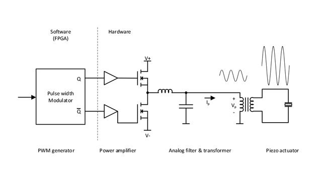
Block diagram of DEMCON’s endo-cutter.
For a surgeon, often the most important feature of a new surgical device is how well it handles during a procedure. While features such as weight, heat, and vibration can be objectively quantified and optimized, the subjective experience of using the device cannot be evaluated until hands-on tests are conducted with early prototypes.
To minimize the time needed to develop a working prototype of a new surgical cutting and drilling device, engineers at DEMCON developed and implemented its control algorithm using Model-Based Design with Simulink® and HDL Coder™. As a result, they reduced overall development time, refined and improved the device based on feedback from surgeons, and quickly accommodated requirement changes late in the project.
“The surgeon is most interested in the endo-cutter’s cutting performance, which is hard to measure as a numerical quantity—the only way to evaluate it is to let surgeons try the instrument,” says Ronald Grootelaar, senior electronics engineer at DEMCON. “With Model-Based Design and the native floating-point features of HDL Coder, we were able to quickly get a working prototype up and running, which made it possible to incorporate feedback from surgeons early in development.”
Challenge
The cutting and drilling instruments on the endo-cutter are driven by a piezo actuator with a class D power amplifier. The actuator is most efficient when operated at its resonant frequency, but that frequency shifts when the instrument comes into contact with tissue during an operation.
DEMCON engineers need to develop a closed-loop controller to keep the piezo actuator at its resonance frequency throughout normal surgical procedures. While some manufacturers use analog controls for this type of application, DEMCON wanted to implement a digital controller to increase efficiency and minimize power dissipation.
Because the controller required numerous input and output channels and had to run at frequencies higher than 1 MHz, the team decided to implement the design on an FPGA rather than on a general-purpose processor. To start tests on hardware as early as possible, the team wanted to generate HDL code instead of writing it by hand.
Solution
DEMCON engineers used Model-Based Design for signal processing, algorithm development, and implementation.
Working in Simulink, the team developed a floating-point model of a proportional integral (PI) controller for a phased-lock loop. This model includes a sine-wave generator to generate the excitation signal for the piezo drive as well as IQ demodulators for the measured voltage and current. The model derives the phase difference between the outputs of the two demodulators and maintains this phase difference at a specific set point.
Recognizing that the dynamics of the actuator would be difficult to model accurately, the team opted to model the plant as a linear system.
They created the plant model in MATLAB® and Simulink, and ran closed-loop simulations of the controller and plant to verify proper locking behavior of the PLL in the presence of noise and to check that it maintained lock for various set points.
At the outset of the project they planned to target a small FPGA. To reduce the amount of programmable logic resource capacity that would be consumed, they converted the Simulink controller model to fixed point.
Once the team had verified the functionality of their initial controller design via simulation, they used HDL Coder to generate synthesizable HDL code from the fixed-point Simulink model.
They deployed the generated code to an FPGA development board to interactively test their control algorithm as it ran on real-time hardware. Using this setup, the team could control design parameters within the FPGA’s programmable logic by changing register values, and get instantaneous feedback on how different parameter values affected controller performance.
As work on the design progressed, the team determined that the FPGA they had chosen had an insufficient number of pins to meet their requirements. They selected a larger FPGA with more pins. Because the larger FPGA also had more logic cells and DSP slices, they had more programmable logic available for their controller.
The DEMCON team decided to take advantage of the additional logic by producing a single-precision floating-point implementation of the controller using the native floating-point capability of HDL Coder. A floating-point implementation gave them more flexibility to tune the controller during testing.
The team experimented with different cutting and drilling instruments on a variety of tissues to verify the prototype’s operation under a range of real-world damping and load conditions. They further improved cutting performance by refining PI controller parameters based on feedback provided by surgeons in subsequent hands-on tests.
Throughout development, DEMCON engineers followed a process that complied with the IEC 62304 standard for medical device software, even though compliance is not formally required for FPGA implementations. As part of this effort, the team used their Simulink model and simulations as a basis for developing unit tests and documentation that mapped to software development process requirements highlighted in IEC 62304.
DEMCON engineers are integrating the controller with the electronics and other hardware as they prepare for tests of the final hardware design.
Results
- Initial prototype completed 7x faster. “When we developed a similar controller algorithm on a previous project, it took weeks or more to hand-code in C for our target DSP,” says Grootelaar. “With Model-Based Design and native floating-point code generation using HDL Coder, we had a prototype up and running in one day.”
- Clock speed requirement met with no manual effort. “The ability to apply clock rate pipelining with HDL Coder was very useful in producing a design that runs at our required clock speed,” Grootelaar says. “It is really difficult to implement pipelining and resource sharing when you write code manually, but HDL Coder makes it easy.”
- Late requirement change implemented in one day. “At a late stage in the project, we received a new requirement for the controller to provide feedback on its own status,” says Rob Reilink, senior mechatronic system engineer at DEMCON. “That kind of change would take at least a week to make with hand coding, but with Model-Based Design, we simply made a minor change to the model and fulfilled the requirement in one day. The ability to implement this kind of change without incurring time and cost overruns was a significant advantage for us.”